Printed circuit card edge connectors are critical components that enable direct, reliable connections between printed circuit boards (PCBs) and mated sockets without additional wiring or intermediate connectors. This article provides a comprehensive overview of card edge connectors—covering working principles, common types, design best practices, and selection criteria—to help engineers optimize reliability and signal integrity in modern electronic systems.
Many designers face challenges when integrating printed circuit card edge connectors, especially in high frequency or high endurance applications. Below are common pain points:
- Poor contact reliability due to insufficient gold plating thickness on the gold finger.
- Impedance mismatch causes signal reflections and data errors.
- Misalignment or mechanical wear after repeated mating cycles.
- Difficulty choosing the right onecard edge connector typefor power or high-speed data.
- Not efficientcard edge connector PCB designleading to manufacturing rework.
To overcome these challenges, advanced design and manufacturing approaches are essential:
- Apply selective hard gold plating (≥3µm) to the gold finger printed circuit card edge connectorfor durability.
- Implements controlled impedance routing and minimizes stub length on the PCB.
- Use the guide feature and reinforced housing inedge connector socket.
- Choose a specialized onecard edge power connector or high speed version based on current/speed requirements.
- Adhere to DFM rules for pad geometry, solder mask clearance, and plating thickness.
At Best Technology, we specialize in high precision PCB manufacturing and assembly, with a focus on reliable supportcard edge connector PCB design. Our capabilities include impedance-controlled multilayer PCBs, precision gold finger plating, and full traceability via MES—all compliant with ISO 9001, ISO 13485, IATF 16949, and AS9100D standards. For a rugged PCB solution tailored to your interconnection needs, don’t hesitate to contact our team at [email protected].
What is a Printed Circuit Card Edge Connector?
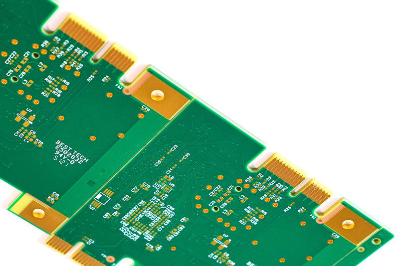
Printed circuit card edge connectors provide a direct interconnect solution in which the edges of the PCB itself—equipped with gold-plated contacts (“gold fingers”)—are inserted into matching sockets. This eliminates the need for separate connector components soldered to the board, saving space and cost while improving signal integrity in high-speed applications.
The main structural elements include:
- Goldfinger: Edge plated contacts on a PCB, usually hard gold over nickel for low resistance and wear resistance.
- Mating Socket: The housing contains spring-loaded contacts that grip the edges of the PCB.
- Polarization and Locking Features: Make sure the board is inserted correctly.
These connectors are widely used in memory modules (DDR), expansion cards (PCIe), and industrial control systems due to their simplicity, reliability, and high-density contact capabilities.
How Do Printed Circuit Board Edge Connectors Work in Electronic Systems?
Aprinted circuit board edge connector works by establishing electrical contact between the gold-plated traces on the edge of the PCB and the corresponding terminals in the socket. When the PCB is inserted, the spring contacts of the socket press firmly against thegold fingercreates a gas-tight connection that minimizes oxidation and maintains stable conductivity over multiple mating cycles.
Signal transmission depends on:
- Consistent contact pressure from the socket spring.
- Low contact resistance due to the excellent conductivity of gold.
- Impedance matching between PCB traces and connector interfaces to prevent reflections.
This makesedge connector socketideal for applications requiring frequent board insertion/removal, such as test fixtures or modular systems.
What Types of Main Card Edge Connectors Are Used in Modern Devices?
Variouscard edge connector type have been standardized to meet specific mechanical, electrical and environmental requirements. Common configurations include:
- PCI Express (PCIe): Used for graphics cards and expansion cards, with varying contact lengths for hot-plug capability.
- DDR Memory Connector: Designed for high-speed data transfer with precisely controlled impedance.
- Industrial Card Edge Connector: Features a sturdy housing and higher mating cycle for harsh environments.
- Wire-to-Board Card Edge Connector: Allows cables to be terminated directly to the edge of the PCB, simplifying assembly.
Selecting the right type depends on factors such as data speed, current capacity, space constraints, and required durability.
What Role Does Gold Finger Play in Printed Circuit Card Edge Connectors?
Gold fingers on printed circuit card edge connectors are critical to maintaining reliable electrical contact and resistance to wear. Gold plating—usually 3–15 µin (0.075–0.38 µm) of hard gold over nickel—provides:
- Low and stable contact resistance, even after thousands of mating cycles.
- Excellent corrosion resistance, essential for maintaining signal integrity in damp or corrosive environments.
- Superior solderability and bond strength to the underlying nickel barrier.
For high frequency or high cycle applications, determining adequate gold and nickel undercoat thickness is critical to preventing fretting wear and corrosion.
How to Optimize Card Edge Connector PCB Design for Signal Integrity?
Proper card edge connector PCB design is critical for high-speed digital and RF applications to minimize signal reflections, crosstalk and degradation. The main considerations include electrical and mechanical aspects.
1. Impedance Control
Match trace impedance to system requirements (e.g., single-ended 50Ω, differential 100Ω) by adjusting dielectric thickness, trace width, and copper weight. Use manufacturer-provided simulation tools to verify impedance before fabrication.
2. Pad and Trace Geometry
Make sure the gold finger pad pitch and length match the connector specifications. Reduce transitions between pads and internal traces to avoid sudden impedance changes that cause reflections.
3. Coating Thickness and Surface Finish
Specify adequate coating for durability and reliable contact: usually nickel 3–5 µm under hard gold 0.5–1.27 µm. This ensures wear resistance and corrosion protection.
4. Solder Mask Clearance
Keep the solder mask away from the gold fingers to prevent poor contact, uneven plating, or insertion interference.
5. Board Edge Slope (Chamfering)
Beveling allows smooth PCB insertion and protects the board and connectors:
- Corner: The default is 30°, although 20°, 45°, or 60° may be required.
- Edge Thickness: The minimum post-bevel thickness should be ≥0.25 mm.
- Depth Calculation:

Where D = PCB thickness, Q = final edge thickness, A = oblique angle.
- Example: D=1.6mm, H=0.3mm, a=30° → L≈1.12mm.
- Additional Features: Alignment notches or contour cuts help secure the board to the connector.
In conclusion, following these guidelines—impedance control, precise layout, adequate coating, solder mask clearance, and proper tilt—ensures signal integrity and reliable mechanical performance. Early collaboration with your PCB manufacturer is critical to meeting all specifications.
When to Choose a Wire-to-Board Card Edge Connector for Power or Data Transmission?
Awire-to-board card edge connectorbeneficial when wiring directly to the edge of the PCB simplifies assembly or improves current handling. Use cases include:
- High Current Applications: Thick cables can be connected directly to the edge of the PCB, supporting higher currents than standard headers.
- Compact Design: Eliminates the need for separate connector traces on the board.
- Vibration Resistant Assembly: Crimped or soldered wires can relieve tension.
This type is common in power supplies, automotive control units, and telecommunications infrastructure where space and reliability are important.
What are the Advantages of Card Edge Power Connectors in High Current Circuits?
Card edge power connector preferred in high power systems because:
- Minimize interconnection bottlenecks by connecting power sources directly to the PCB.
- Supports high current ratings (up to tens of amps per contact) with robust plating and sufficient trace width.
- Reduces the number of components and assembly steps compared to separate terminal blocks.
They are widely used in server power distribution, industrial motor drives, and renewable energy systems.
How to Choose the Best Printed Circuit Card Edge Connector for Your Project?
Selecting the best printed circuit card edge connector involves evaluating:
- Current Rankings: Make sure the connector meets or exceeds the maximum current, with reduced temperature.
- Coating Material and Thickness: Hard gold for high cycle applications; Selective coating to reduce costs.
- Mechanical Durability: Check the specifications of the mating cycle and the strength of the house material.
- Environmental Compliance: Confirm ratings for temperature, humidity and vibration.
Always validate the selected connector based on industry standards and real-world operating conditions.
Why Choose the Best Technology for High Precision PCB Manufacturing Support Card Edge Connectors?
At Best Technology, we combine advanced PCB fabrication with stringent process controls to ensure your printed circuit card edge connectors perform reliably in the most demanding applications. Our strengths include:
- Precision multilayer PCB production with tight impedance tolerances (±10%).
- Accurate gold finger plating with controlled thickness and smooth beveling.
- Full traceability via MES and certifications including IATF 16949, ISO 13485 and AS9100D.
We help customers achieve consistent connector alignment, signal integrity and long-term reliability. Don’t hesitate to contact our team at [email protected] to discuss your Card Edge power connector PCB project requirements.
In short, printed circuit card edge connectors remain a robust and cost-effective solution for board-level interconnections in modern electronics. By understanding the types, design rules, and material requirements, engineers can improve system performance and durability. Best Technology supports this goal with high-precision PCB manufacturing, strict quality assurance, and extensive industry expertise. For reliable PCB edge connector solutions, feel free to contact us at [email protected].
Tag: printed circuit card edge connector, Printed Circuit Card Edge Connector, gold finger printed circuit card edge connector
This entry was posted on Wednesday, November 12, 2025 at 10:28 am and is filed under best pcb, best pcb. You can follow any responses to this entry via the RSS 2.0 feed. You can skip to the end and leave a response. Ping is currently not allowed.
News
Berita
News Flash
Blog
Technology
Sports
Sport
Football
Tips
Finance
Berita Terkini
Berita Terbaru
Berita Kekinian
News
Berita Terkini
Olahraga
Pasang Internet Myrepublic
Jasa Import China
Jasa Import Door to Door
Originally posted 2025-11-12 05:58:19.