How do you choose a PCB connector header that fits the board layout, mating part, current load, and assembly process? This small connector often looks simple, but it can affect signal stability, power delivery, service access, and final assembly quality.
A PCB header connector is widely used in control boards, sensor modules, display boards, power boards, communication modules, and test fixtures. This guide explains how it works, what types are available, which specifications matter, and how to select a suitable part for different use cases.
What Is PCB Connector Header?
A PCB connector header is a board-mounted connector used to link a PCB with another board, cable, module, sensor, display, or external device. It usually contains metal pins fixed inside a plastic housing.
The pins create the electrical path, while the housing keeps the pin spacing stable. A header can mate with a female socket, wire housing, ribbon cable connector, or another board-level connector.
In practical PCB design, a header PCB connector is often selected because it is simple, affordable, and easy to assemble. It can support signal transmission, low-voltage power, debugging, programming, and modular product design.
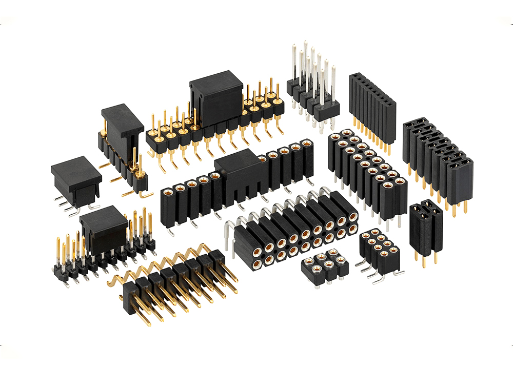
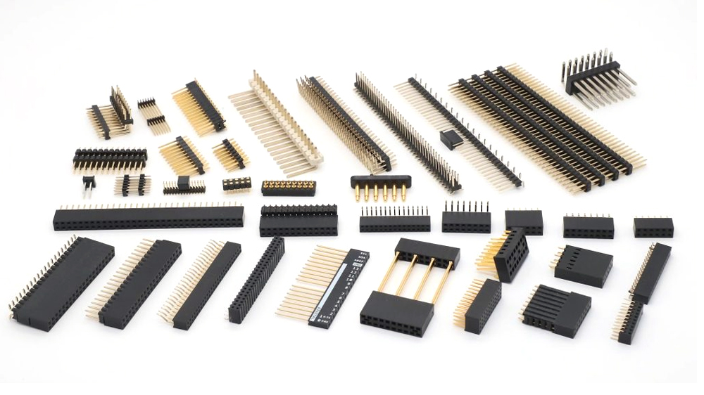
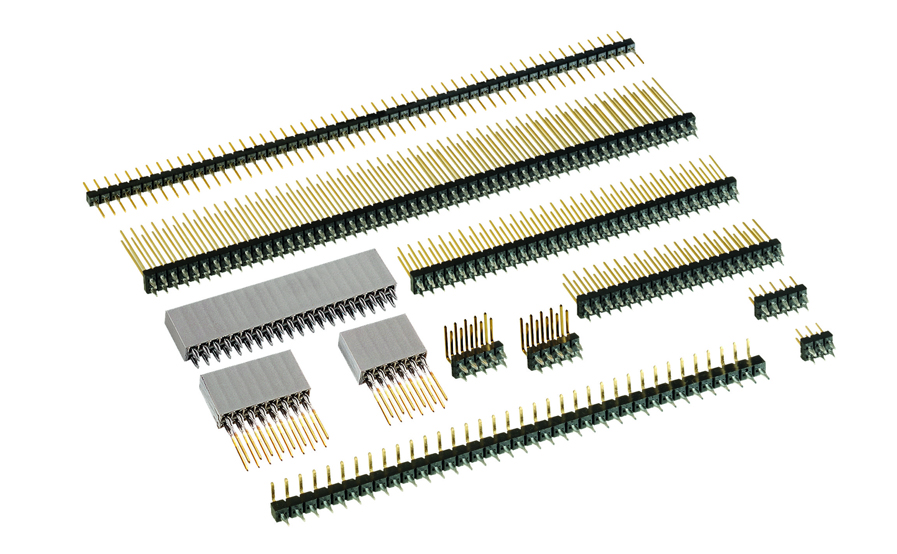
PCB header connectors are available in many forms, such as straight, right-angle, single-row, double-row, shrouded, surface-mount, and through-hole versions. The correct choice depends on space, current, mating direction, and assembly method.
How Does a PCB Connector Header Work?
A PCB connector header works by creating a fixed conductive interface between the PCB copper circuit and a mating connector. Once soldered to the board, the header pins become an extension of the circuit, allowing signals or power to pass through a detachable connection.
- Metal pins carry current or signals
Each pin connects to a PCB pad or plated hole. The pin may carry power, ground, data, control signals, or test signals. - Plastic housing controls alignment
The housing keeps all pins in the correct position and spacing. This helps the mating connector insert smoothly. - Solder joints fix the header to the PCB
Through-hole pins pass through drilled holes and are soldered on the opposite side. SMT pins are soldered directly onto surface pads. - The mating connector completes the link
A female socket, cable housing, IDC connector, or board socket grips the pins and creates a removable electrical path. - The layout controls long-term reliability
Pad size, hole diameter, copper width, clearance, and connector position all affect final performance.
What Are Types of PCB Header Connector?
PCB header connector types are mainly divided by row structure, mounting direction, housing design, and assembly method. Before choosing a part, compare its structure with the board design and the final product enclosure.
- Single-row header
This type has one line of pins. It is common in sensor boards, small modules, power pins, and simple signal interfaces. - Double-row header
This type has two parallel rows of pins. It provides more connections in a smaller board area and is often used for programming ports, control boards, and board-to-board links. - Straight header connector
The pins stand vertically on the PCB. It is useful when the mating board or cable connects from above. - Right-angle header connector
The pins bend at 90 degrees. This type is useful when the cable or mating board exits from the side of the PCB. - Shrouded header connector
A plastic wall surrounds the pins. It improves alignment and helps reduce wrong insertion when used with a matching housing. - Box header connector
This connector is commonly used with ribbon cable assemblies. It is widely seen in industrial control boards and internal equipment wiring. - Breakaway pin header connector
This header can be cut to the needed pin count. It is often used in early testing, development boards, and flexible low-volume builds. - SMT PCB mount header connector
This surface-mount type saves board space and fits automated assembly. It is suitable for compact electronics. - Through-hole PCB mount header connector
This type offers stronger mechanical support. It is often preferred for repeated plugging, heavier cables, and industrial products.
What Technical Parameters to Check for PCB Header Connector Selection?
Before selecting a PCB header connector, compare the electrical rating, mechanical dimensions, mounting method, and mating compatibility. A small difference in pitch, pin length, plating, or housing height can affect PCB layout, assembly fit, and long-term connection stability.
| Technical Parameter | Selection Requirement |
|---|---|
| Pin Pitch | Confirm 2.54mm, 2.00mm, 1.27mm, 1.00mm, or other required spacing |
| Number of Positions | Select the correct 2 pin, 3 pin, 4 pin, 6 pin, 10 pin, or multi-pin layout |
| Row Configuration | Choose single-row or double-row structure according to connection density |
| Mounting Type | Select through-hole, SMT, or right-angle mounting based on PCB layout and assembly method |
| Current Rating | Check the rated current per contact, especially for power or load-carrying circuits |
| Voltage Rating | Confirm the maximum operating voltage for the circuit design |
| Contact Resistance | Review the maximum contact resistance value for stable signal or power transfer |
| Insulation Resistance | Check the insulation resistance between adjacent contacts |
| Contact Plating | Choose tin, gold flash, or selective gold plating according to mating life and signal stability |
| Pin Length | Confirm both solder tail length and mating pin length |
| Mating Height | Check the connected height after mating with the female header or socket |
| Housing Material | Confirm PBT, PA, LCP, or high-temperature plastic based on assembly conditions |
| Operating Temperature | Match the rated temperature range to the final working environment |
| Mating Cycles | Check the rated insertion and withdrawal cycles for removable or test interfaces |
| Packaging Method | Confirm tape-and-reel, tube, tray, or bulk packaging according to production method |
How to Choose the Right PCB Connector Header?
Choosing the right PCB connector header starts with the actual board design, not only the connector appearance. Pin pitch, mounting style, current rating, mating direction, housing structure, and available space should all match the PCB layout and final assembly method.
- Check the connection purpose first
Confirm whether the header is used for signal transfer, power connection, board-to-board connection, cable-to-board connection, debugging, or testing. Different uses require different pin size, pitch, and mechanical strength. - Select the correct pin pitch
2.54mm pitch is common for general boards, test ports, and simple signal interfaces. 2.00mm and 1.27mm pitch are better for compact products. The selected pitch must match both the PCB footprint and the mating connector. - Match the pin count and row structure
Choose the number of positions according to the required power, signal, ground, and control lines. Single-row headers are suitable for simple connections, while double-row headers help save space when more contacts are required. - Choose the right mounting style
Through-hole headers provide stronger mechanical support and are suitable for cable movement, repeated plugging, or larger connectors. SMT headers save PCB space and fit automated assembly. Right-angle headers are useful when the cable or mating board exits from the side. - Confirm the current and voltage rating
For power-related connections, check the rated current per contact, rated voltage, pin size, copper width, and solder joint area. The connector should support the circuit load without excessive temperature rise. - Check the mating connector carefully
Do not compare pitch alone. Pin size, insertion depth, housing shape, row spacing, latch design, and mating height should also match. A PCB pin header connector and its female socket should be confirmed as a compatible pair before layout is finalized. - Consider the working environment
For industrial control, LED lighting, automotive electronics, outdoor equipment, or high-temperature products, check operating temperature, housing material, plating, and soldering compatibility. High-temperature plastic is more suitable for reflow assembly. - Review the available board and enclosure space
Check connector height, cable bend direction, mating clearance, and nearby components. The connector should be easy to insert and remove without touching tall parts, heat sources, or enclosure walls. - Choose suitable contact plating
Tin plating is suitable for many standard applications. Gold flash or selective gold plating is better for repeated plugging, low-level signals, and more stable contact performance. - Verify assembly and inspection requirements
Confirm whether the connector packaging supports the planned assembly process, such as tape-and-reel, tube, tray, or bulk packaging. After assembly, inspect alignment, solder joints, pin condition, and mating fit.
How to Mount PCB Pin Header Connector Correctly?
A PCB pin header connector must be mounted with the correct footprint, orientation, soldering method, and inspection process. Poor mounting can lead to loose pins, weak solder joints, intermittent signals, or difficult mating.
1. Confirm the footprint before PCB layout
Check pitch, hole diameter, pad size, row spacing, pin length, and connector outline against the datasheet.
2. Mark Pin 1 clearly
Add a clear Pin 1 mark on the PCB silkscreen. For power headers, mark positive, negative, voltage, or ground direction.
3. Reserve enough clearance
Keep space around the connector body for mating, unmating, fingers, cable bend radius, and nearby components.
4. Match the mating connector
Do not judge only by pitch. Check pin shape, insertion depth, housing shape, and mating height.
5. Choose the right soldering method
Through-hole headers usually use wave soldering or hand soldering. SMT headers are commonly mounted by reflow soldering.
6. Control connector alignment
The header should sit straight before soldering. Tilted pins may cause poor mating or mechanical stress.
7. Inspect solder joints after assembly
Look for insufficient solder, bridging, pin movement, tilted housing, and damaged plastic.
8. Test the connection after assembly
For important products, perform continuity testing, functional testing, and visual inspection before shipment.
Where Are PCB Header Connectors Commonly Used?
PCB header connectors are commonly used where a PCB needs a removable, modular, or testable connection. They make board connection, testing, replacement, and modular assembly easier in many electronic products.
- Industrial control boards
- LED lighting control boards
- Power supply boards
- Sensor modules
- Communication modules
- Battery management systems
- Display boards
- Medical electronics
- Automotive electronics
- Robotics and automation boards
- Test fixtures and programming boards
Which Suppliers Provide PCB Header Connectors?
Many global connector brands provide PCB header connectors in different pitches, pin counts, mounting styles, and material grades. When selecting a supplier, compare datasheets carefully and confirm availability before final PCB layout.
- TE Connectivity: Offers many board-level connectors, including headers, receptacles, wire-to-board parts, and board-to-board connector families.
- Molex: Provides pin headers, wire-to-board connectors, board-to-board connectors, and custom connector solutions for many electronics fields.
- Samtec: Known for board-to-board headers, sockets, high-speed connectors, and flexible stack height solutions.
- Amphenol: Supplies PCB connectors, board-level interconnects, rugged connectors, and industrial connector families.
- JST: Commonly used for wire-to-board connectors, compact headers, and cable assembly interfaces.
- Hirose: Offers compact board-to-board, wire-to-board, and fine-pitch connector families.
- Harwin: Provides PCB headers, high-reliability connectors, and board-level interconnect products.
- Würth Elektronik: Supplies board connectors, terminal blocks, pin headers, and electronic interconnect products.
- Phoenix Contact: Well known for PCB terminal blocks, industrial PCB connectors, and control cabinet connection products.
- 3M: Provides IDC connectors, ribbon cable connectors, and board interconnect products.
For purchasing, it is better to use traceable supply channels and confirm the exact manufacturer part number. For shortage or discontinued parts, compare footprint, pitch, pin size, plating, current rating, and mating compatibility before approving any substitute.
FAQs About PCB Header Connectors
Q1: How do I know which PCB header connector pitch to choose?
A1: Start from the PCB layout space and the mating connector. 2.54mm pitch is common for general signal and development boards, while 2.00mm, 1.27mm, or smaller pitch is better for compact products. The pitch must match the PCB footprint and the female socket or cable housing.
Q2: Can I use a 2 pin PCB header connector for power input?
A2: Yes, a 2 pin PCB header connector can be used for low-voltage power input, LED connection, battery connection, or simple DC output. Before use, check the rated current, rated voltage, copper width, solder joint area, and polarity marking.
Q3: When should I choose a straight header instead of a right-angle header?
A3: Choose a straight header when the mating connector plugs in from the top of the PCB. Choose a right-angle header when the cable or mating board exits from the side. The final choice depends on enclosure space, cable direction, and assembly access.
Q4: Is a through-hole header stronger than an SMT header?
A4: In most cases, a through-hole header offers better mechanical support because its pins are inserted through the PCB and soldered into plated holes. SMT headers are more suitable for compact boards where space saving and automated assembly are more important.
Q5: How can I avoid choosing the wrong female connector for a pin header?
A5: Do not compare pitch alone. Check pin size, mating depth, plastic height, row spacing, housing shape, and insertion direction. A PCB pin header connector and its female connector should be confirmed as a matched pair before PCB layout is finalized.
Q6: What plating should I choose for a PCB connector header?
A6: Tin plating is suitable for many standard applications. Gold plating is better for signal stability, lower contact resistance, and repeated mating. For test ports, programming ports, or removable modules, gold flash or selective gold is often a better choice.
Q7: What should be checked before using an alternative PCB header connector?
A7: Compare the original and alternative parts carefully, including pitch, pin count, row configuration, pin length, mating height, PCB footprint, current rating, voltage rating, plating, and housing material. A similar appearance does not always mean the parts are interchangeable.
Conclusion
Choosing the right PCB connector header is not only about pin count. Pitch, mounting style, current rating, plating, housing type, mating height, and PCB layout all affect final performance. A well-matched connector helps the board stay easier to assemble, easier to test, and more stable in daily use.
If you are preparing a PCB or PCBA project with header connectors, send us your BOM, PCB files, and assembly requirements for review. EBest can support component sourcing, PCB fabrication, SMT assembly, through-hole assembly, soldering quality control, inspection, testing, and production support. Contact us at [email protected] for a fast quotation.
Tags: header pcb connector, pcb connector header, pcb header connector types, pcb header connectors, pcb pin header connector
PakarPBN
A Private Blog Network (PBN) is a collection of websites that are controlled by a single individual or organization and used primarily to build backlinks to a “money site” in order to influence its ranking in search engines such as Google. The core idea behind a PBN is based on the importance of backlinks in Google’s ranking algorithm. Since Google views backlinks as signals of authority and trust, some website owners attempt to artificially create these signals through a controlled network of sites.
In a typical PBN setup, the owner acquires expired or aged domains that already have existing authority, backlinks, and history. These domains are rebuilt with new content and hosted separately, often using different IP addresses, hosting providers, themes, and ownership details to make them appear unrelated. Within the content published on these sites, links are strategically placed that point to the main website the owner wants to rank higher. By doing this, the owner attempts to pass link equity (also known as “link juice”) from the PBN sites to the target website.
The purpose of a PBN is to give the impression that the target website is naturally earning links from multiple independent sources. If done effectively, this can temporarily improve keyword rankings, increase organic visibility, and drive more traffic from search results.
