If you have ever seen a multimeter for the first time, dial filled with symbols can look extraordinary. For beginners, these icons are often the most confusing part of this tool. However, understanding the multimeter symbol is very important. Each symbol tells you what is ready to be measured – whether it is voltage, current, resistance, continuity, or even more advanced functions such as capacitance and frequency.
Multimeter is not just for professionals. Home users, electric artisans, and electronic fans all rely on it to diagnose problems, test components, and ensure safety in electricity. If you don’t know what the symbol means, you are at risk of the wrong measurement or damaging the tool. This guide will guide you through the meaning of each symbol, how to use it step by step, and practical techniques for daily testing.
What does the symbol mean to the multimeter?
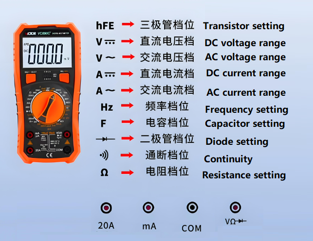
Each multimeter has a spinning dial or digital menu with symbols. This represents the measurement mode. After you learn it, the multimeter becomes easier to use. Let’s explore the most common:
| Symbol | Function | Fast Note / meaning |
| V ~ | AC voltage | Alternating current voltage |
| V- or VDC | DC voltage | Direct current voltage |
| A ~ | AC current | Alternating current measurements |
| A- or ADC | DC current | Direct current measurement |
| Oh | Resistance | Steps in Ohm |
| ** Diode (▶ | -) ** | Diode test |
| Continuity (🔔 or ~)) | Continuity | BIP if the circuit is complete |
| ** | ** | |
| Hz | Frequency | AC signal frequency in Hertz |
| MV | “ | Small voltage measurement |
| μA / MA | AMP Micro / Milli | Small current range |
| Through the hole | Connection examination | All testing of layers (for PCB) |
Here is a table so that it is clearer to understand each symbol in a multimeter:
How to use a multimeter for beginners?
If you are new to a multimeter, don’t worry. The following is the simple step by step approach that applies to most models:
1. Enter the probe correctly. Black leaders always enter the Port com (general). Red lead enters the port marked V voice for most tests. For high current measurements, use a special 10A or 20A port.
2. Turn dial. Choose a symbol for what you want to measure. For voltage, select AC (V ~) or DC (V—). For resistance, use Ω.
3. Connect the probe. Place the ends at two points of the circuit. For voltage, measure components. For now, enter the meter in series. For continuity, just touch both ends of the conductor.
4. Read the screen. Digital multimeter will give you an instant number. If the amount seems unstable, try to switch to another range.
Beginners must practice first in a safe and low -voltage circuit. For example, the battery test in DC mode. This builds confidence before working with a direct AC circuit.
How to read the multimeter display?
Multimeter display shows more than just numbers. Understanding indicators will increase accuracy.
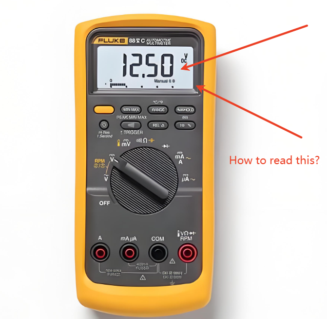
- Numerical reading: The clearest part. This is the value you measured.
- Unit Indicator: Letters or symbols such as V, A, or Ω appears next to the reading. This shows what is represented by that number. Display display v means this value is voltage, facility current, Ω means resistance.
- Indicator range: A few meters show the prefix such as M (milli), μ (micro), or K (kilo). For example, 1.2KΩ means 1,200 ohms.
- Additional icons: Many meters have small indicators for functions such as “resistant,” “low battery,” or “automatic range.”
If you use a manual multimeter range, you also need to match the dial with the expected value. For example, if you measure the 9V battery, set the range above 9V (maybe 20V). Multimeter Automatically saves time by choosing the correct range for you.
Which AC and DC in a multimeter?
Multimeter clearly distinguishes AC and DC from different symbols:
- AC is displayed with v ~ or ~. Corrugated lines match the alternating AC signal pattern.
- DC is displayed with V— or A-. Straight and broken lines -Putus representing constant flow in one direction.
This difference is very important. Using DC mode on AC outlets, for example, will not give you reliable reading. Even worse, can damage the meter if arranged incorrectly in the current mode. Always confirm the source before selecting AC or DC.
What is good reading for continuity?
Continuity examination is one of the easiest tests with a multimeter. When continuity exists, resistance is close to zero. Good reading usually:
- 0 to 2 ohms: strong connection.
- BIP Sound: Most of the meters sounded when there was continuity.
- OL or no reading: This shows an open circuit, which means there is no path for current.
For example, if you test the wire and hear the bip sound, that means the wire is intact. If there is no sound, the wire is damaged. This test is useful for checking the fuse, traces of PCB, and connectors.
What is one thing you can’t do when using a multimeter?
The most important safety rules: Never measure resistance in the live circuit. Resistance testing requires a multimeter to send small currents through the circuit. If the circuit is powerful, this can damage the meter or give the wrong results.
Other things to avoid:
- Don’t exceed the current meter ranking. Always check the specifications.
- Never switch fashion when the probe is connected to the live circuit.
- Do not touch the tip of the probe when measuring high voltage.
- Safe habits to keep users and multimeters protected.
How do I know what settings will be used on a multimeter?
Choosing the right setting depends on the work. Here are some quick tips:
- Battery testing: Use V – (DC voltage).
- Outlet testing: Use V ~ (AC voltage).
- Check the resistor: Use Ω.
- Checking the fuse or wire: use continuity (buzzer symbol).
- Test diode or LED: Use diode mode.
If you are not sure, always starting from the highest range for the arrangement, then lower. This prevents overload and protecting meters. Automatic range models eliminate this step but still good practice to know.
How do I tell the voltage with a multimeter?
Voltage is one of the most common tests. This is how to measure it:
- Adjust the multimeter to the correct type of voltage (AC or DC).
- Connect the black probe to the probe com and red to vωma.
- Place the probe across components or sources. For batteries, red becomes positive, black to negative.
- Read the screen. Digital meters show their value directly; Analog meters need to read needles to the scale.
Voltage reading shows the potential difference between two points in a circuit. For security, ranking confirmation and type of voltage before connecting probe.
How do you tell me whether power is an air conditioner or DC with a multimeter?
If you are not sure about the type of power, a multimeter can help identify it:
- Set the meter to the AC voltage (v ~). Measure voltage.
- If the reading is zero, turn to DC (V—).
- If the value appears in DC mode, the circuit uses a direct current. If it appears in AC mode, it’s alternating current.
Some multimeters have automatic AC/DC detection features, showing the type automatically. This is useful for testing sources that are not known safely.
For example, household outlets must provide reading in AC mode, while the battery will only be displayed in DC mode. This method can be relied upon when testing unknown power supply.
FAQ
1. What is the diode symbol on the multimeter used?
This is used to test whether the current flows in one direction, especially for diodes or LEDs.
2. Can I measure the AC voltage on the battery?
No. The battery provides DC only. AC mode will not show useful reading.
3. Why are continuity testing important?
It checks whether the circuit line is complete. This helps detect damaged cables, damaged fuses, or wrong connections.
4. What does “OL” mean to the multimeter?
It is an abbreviation of “Open Loop.” This shows unlimited resistance, which means the circuit is damaged.
5. Can I use the same probe for voltage and current tests?
Yes, but for high currents, enter the red probe into a special high -current port.
Studying a multimeter symbol may look like a small step, but it opens the real power of this tool. After you know what the meaning of each symbol, voltage testing, current, resistance, and continuity becomes the second nature. For beginners, starting with a low -voltage DC test is the best way to build confidence. Over time, you can handle AC circuits, diodes, capacitors, and even frequency tests.
In the best technology, we support customers with high quality testing tools and professional PCB solutions. Our products come with tight quality control below ISO9001, ISO13485 for medical, IATF16949 for Automotive, and AS9100D for Dirgantara Standards. By combining competitive prices, skilled engineering, and tracking through the MES system, we provide reliable solutions for each customer. Whether you need a PCB or a reliable test tool, we provide everything with precision and maintenance.
Tags: Multimeter symbols in the circuit, multimeter symbol
This entry was posted on Monday, September 15, 2025 at 10:44 am and was submitted under the best PCB, BestTPCB, FAQ, PCB News. You can follow any response to this entry through RSS 2.0 bait. You can jump to the end and leave a response. Pinging is currently not permitted.
News
Berita
News Flash
Blog
Technology
Sports
Sport
Football
Tips
Finance
Berita Terkini
Berita Terbaru
Berita Kekinian
News
Berita Terkini
Olahraga
Pasang Internet Myrepublic
Jasa Import China
Jasa Import Door to Door
Originally posted 2025-09-15 04:01:15.