Why choose 1 layer of MCPCB For outdoor solar cells? “This guide explores its structure, thermal excellence, and increased reliability for a hard environment.
Solar energy innovator: “Are you struggling with:
- Loss of heat induced efficiency in an outdoor solar array?
- Slow prototypes delay your-market-time?
- Environmental degradation shortens product life?
The best technology can give you:
- 24 -hour fast prototype – Accelerate R&D Cycles
- The thermal paths optimized by Ultra-40% Better Heat Discipline vs. Standard Board
- Aerospace-Class Power-IP68 aluminum substrate holds UV/Moist/IP68 salt spray
Ask for your free thermal simulation report today: [email protected].
What is 1 layer of MCPCB?
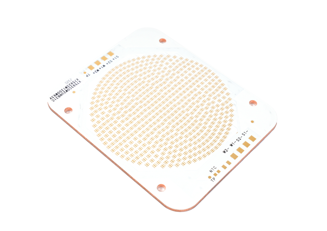
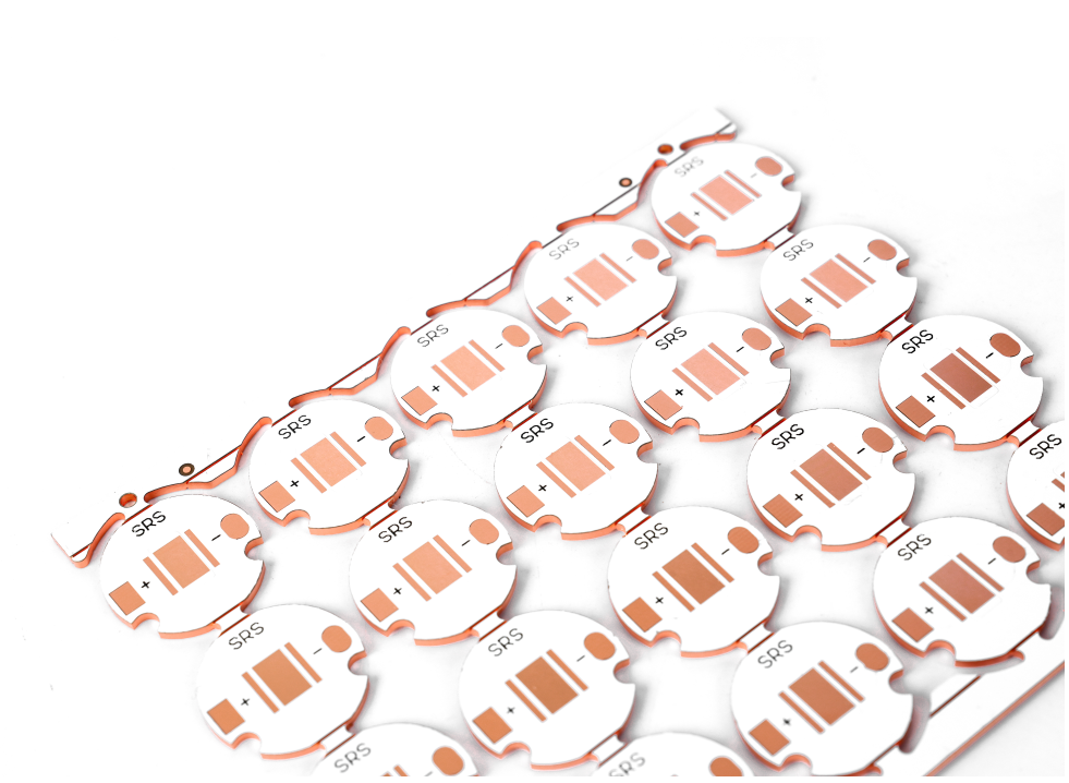
A 1 layer of MCPCB (Metal Core Printed Circuit Board) is a special circuit board that displays a single conductive copper layer bound to the metal substrate, usually aluminum. Metal core efficiently transfer heat from components, making it ideal for high power applications where thermal management is very important.
This structure consists of three main parts: the base of the metal for heat dissipation, the dielectric layer for electrical insulation, and a single copper layer for the circuit. This design ensures effective cooling while maintaining electrical insulation. Although simpler than a multi-layer board, it offers excellent thermal performance for LED lighting, power electronics, and automotive systems.
With its direct layout, 1 MCPCB layer balances the effectiveness and reliability of the cost, making it a preferred choice for heat sensitive electronics that require efficient endurance and thermal regulations.
How thick is 1 layer of MCPCB?
The following is the structured damage of the typical thickness specifications for 1 layer of MCPCB:
Metal core thickness
- The base metal layer (usually aluminum) usually ranges from 1.0mm to 3.0mm, with 1.5mm and 2.0mm most common for standard applications.
- A thicker core (for example, 3.0mm+) can be used for extreme heat dissipation needs.
The thickness of the dielectric layer
- The insulation layer between metal and copper core ranges from 50 μm to 150 μm (0.05mm to 0.15mm).
- Thinner dielectric increases heat transfer but requires proper manufacturing.
The thickness of the copper layer
- A single conductive copper layer is generally 1oz (35 μm) or 2oz (70 μm) but can rise to 3oz+ for high current design.
Overall thickness of the board
- Total thickness usually falls between 1.2mm to 3.2mm, depending on the combined layer.
- Example: aluminum nucleus 1.5mm standard + 100 µm dielectric + 1oz copper â ‰ ˆ 1.6mm total.
Customization factor
- Thickness can be adjusted based on thermal, mechanical, or electricity needs.
- The thinner board is in accordance with the compact design, while the thicker variant increases the stiffness and heat spread.
What is the dielectric layer of 1 MCPCB layer?
The dielectric layer in the “1 MCPCB” layer functions as an electrical but thermal conductive interface between metal nuclei and copper circuit layer. Here ‘Structure Structure Characteristics:
- Main Function: Isolates Electric Copper Circuit from metal base (usually aluminum) while efficiently transferring heat from components to metal core.
- Material composition: Often consists of polymer -based composite (for example, epoxy resin) which is filled with thermal conductive ceramics (alumina, boron nitride) to increase heat dissipation.
- Thermal performance: Anisotropic micro -structure in sophisticated dielectric layers can increase thermal diffusivity by optimizing filling connectivity, reducing thermal resistance in high power applications.
- Thickness range: Usually measuring 50â € “150 μm (0.05â €” 0.15mm), balances electrical isolation and thermal transfer efficiency.
- Impact on LED performance: Inefficient dielectric layers can cause higher intersection temperatures on LEDs, reduce output and radiant efficiency.
What’s the use of 1 layer of MCPCB?
Use 1 layer of MCPCB:
- LEDs are high -The heat away from the LED, keep it cold for brighter and durable light.
- Electronic power – Managing heat on devices such as inverters or motor drivers, ensuring stable performance under heavy loads.
- Automotive system – Heat resistant and vibration in car lights or control units, even in difficult conditions.
- RF/Microwave device – Reducing excess heat on the radio or antenna, maintaining clear signal strength.
- Solar equipment -Maintaining the controller or inverter controlling solar power is efficient by dealing with the heat produced by sunlight.
- Industrial sensor – Durable design for factory sensors exposed to hot, dust, or movement.
- Compact gadget -Slimpap, hot friendly for laptops or game devices with strong chips.

Why choose 1 layer of MCPCB for outdoor solar cells?
- Heat Discussion: Metal core efficiently perform heat from solar cells, prevent excessive heat and maintain optimal conversion efficiency even in direct sunlight.
- Temperature stability: Resistant to outdoor temperature fluctuations, reduce thermal voltage on components and ensure consistent performance during the night cycle.
- Endurance in hard conditions: Hold the humidity, dust, and UV exposure, making it suitable for external use without degradation.
- Cost -effective design: A simpler structure reduces production costs while still providing reliable thermal management for solar applications.
- Enhanced lifespan: By keeping the components cooler, it reduces wear, extend the operational life of the solar filling system or inverter.
How to increase 1 layer of MCPCB of heat dissipation to extend the life of outdoor solar cells?
- Select High Conductivity Substrate: Use copper (385 W/Mâ · K) for the metal core if it is weight possible. For lighter buildings, choose aluminum 1.5mm+ thick (237 W/Mâ · K) with the final layer of matte to increase radiation cooler in the sun.
- Use advanced dielectric material: Replace standard epoxy with polyimide filled with ceramics (1.5â € “3 W/Mâ · K) in the isolation layer. This cuts thermal resistance of 40â €” 60%, accelerating heat transfer to the substrate.
- Maximize thermal through efficiency: VIAS Drill Copper 0.3mm under the heat -producing component (for example, diode, MPPT chip) at a distance of 1mm. Adjust Vias in a lattice pattern to make a vertical hot path.
- Integrate passive cooling elements: Install the synipped aluminum heat sync (10’m) to the back of the MCPCB. In a compact space, use graphite sheets (1,500 W/Mâ · K) or steam space to spread heat evenly throughout the substrate.
- Apply the emissivity enhancer: Cover the exterior of the core metal with black ceramic paint (emissivity> 0.85). This increases infrared radiation, helping the board spill heat faster in direct sun exposure.
- Optimize component layout: Place high power components (for example, transistors) from the active zone of solar cells. Use thermal gap bearings (2â € “4w/mâ · k) to ensure direct contact between the parts and surfaces of the MCPCB.
- Validation with thermal modeling: Use Ansys Icakak or similar tools to simulate heat flow. Adjust through the pattern, material thickness, or component position based on hotspot analysis (for example, reduce the distance at 50 ° C+ zone).
How do I increase the reliability of MCPCB 1-Lapis for external solar cells?
Choose a long -lasting material
- Use aluminum (light, corrosion resistant) or copper (high conductivity) for metal core. Attach it with a dielectric layer of polymide epoxy or modified to withstand moisture and delamination while ensuring efficient heat transfer.
Improve thermal performance
- Increase thermal through the density under high heat components (for example, a sun charge control) to direct heat to the base of the metal. Think the substrate (for example, aluminum 2mm) or add external heat sinks for passive cooling, reducing the dependence of the active system.
Apply a protective coating
- The coat circuit with UV -resistant conformal waterproof coating (for example, silicon for coastal areas) to protect the solder connection and traces of moisture, dust, and salt spray.
Use a strong component
- Select the outer ranking parts (for example, capacitors rated for -40 ° C to 125 ° C) and high reliability solder (for example, SAC305).
Strengthening the design and test
- Match the dielectric layer CTE with metal and copper traces to prevent cracks. Safe edges with epoxy or fasteners for vibration resistance. Validation with 1,000+ hours 85 ° C/85%RH RH heat, thermal shocks (-40 ° C to 125 ° C), and salt spray tests.
How to increase the durability of MCPCB 1-Laris for hard outdoor conditions?
Use corrosion resistant substrate
- Choose aluminum anodized (alloy 5052) for coastal or industrial areas. Anodization creates a layer of oxide 5 “25” which rejects salt and humidity. In an extreme corrosion environment, select 316 stainless steel despite the higher weight.
Apply multi-layer protective coating
- Circuit coat with a 50 “100” silicone-based layer (for example, Dow Corning 1-2577) to block moisture and dust. Add the acrylic coat 20â € “30 μm for scratch resistance, focus on the solder connection and exposed traces.
Strengthen mechanical stability
- Thicken the dielectric layer to 100 μm polyimide to reduce flexibility under thermal pressure. Edge board is the same as epoxy adhesive or kariman aluminum to fast warping from the source of stume (-40 ° C to 125 ° C) or vibration.
Select outdoor ranking components
- Use capacitors, resistors, and connectors that are ranked IP67 with an operation range of -40 ° C to 125 ° C. Choose gold -coated contact for connectors to hold stains in a humid environment.
Match the thermal expansion nature
- Choose a dielectric layer with a coefficient of thermal expansion (CTE) close to aluminum (23â € “24 ppm/° C). Polyimide filled with ceramics (CTE 12 â €” 18 ppm/° C) Reducing voltage on copper traces during temperature fluctuations.
Validation with accelerated aging
- Perform a thermal cycle of 2,000 hours (-40 ° C to 125 ° C, 1 hour residence) and a 96 hour salt spray test (ASTM B117). Include UV exposure (ISO 4892-3) to confirm the integrity of the coating in prolonged sunlight.
Conclusion
In short, 1 MCPCBS layer provides efficient thermal management solutions for outdoor solar cells with optimized metal core structures, dielectric layer design, and increased durability features. By increasing heat dissipation through material selection and layout optimization, this board significantly extending the life of solar cells while holding back hard environmental conditions. For projects that require rapid turnover and reliable performance, our adjusted 1-lapi MCPCB solution offers a perfect balance of cost effectiveness and thermal efficiency. Contact us today for competitive deals: [email protected].
Tags: 1 MCPCB layer, 1 MCPCB layer for outdoor solar cells, MCPCB
This entry was posted on Friday, July 4, 2025 at 3:13 pm and submitted under the best PCB, BestTPCB, MCPCB, PCB Core Metal. You can follow any response to this entry through RSS 2.0 bait. You can leave a response, or trackback from your own site.
Game Center
Game News
Review Film
Berita Olahraga
Lowongan Kerja
Berita Terkini
Berita Terbaru
Berita Teknologi
Seputar Teknologi
Berita Politik
Resep Masakan
Pendidikan
Berita Terkini
Berita Terkini
Berita Terkini
review anime
Gaming Center
Originally posted 2025-07-05 13:41:57.