Why choose 4 layers of MCPCB For LED UVC? “This guide explores the optimized thermal structure and pathway, the efficiency and reliability of superior LEDs.
Are you having a problem with the problem of heat dissipation from UVC LED?
- High temperatures cause fast decay of light, short life and unstable performance?
- Inadequate heat dispedation from traditional PCB affects product reliability?
The best technology provides:
- The design of very efficient heat dissipation-4 copper layers + optimized heat conduction paths, rapid heat discipline and lower intersection temperatures
- Live stable and long-decay of light decay and make sure UVC LED operations are long-term and efficient
- SAVE SOLUTION COSTS OF BALANCE AND PERFORMANCE TO HELP YOU IMPROVE PRODUCT POWER
Say goodbye to problems that are too hot and make your UVC LED performance more stable and live longer! Consult now to get exclusive heat dissipation optimization solutions: [email protected].
What are 4 layers of MCPCB?
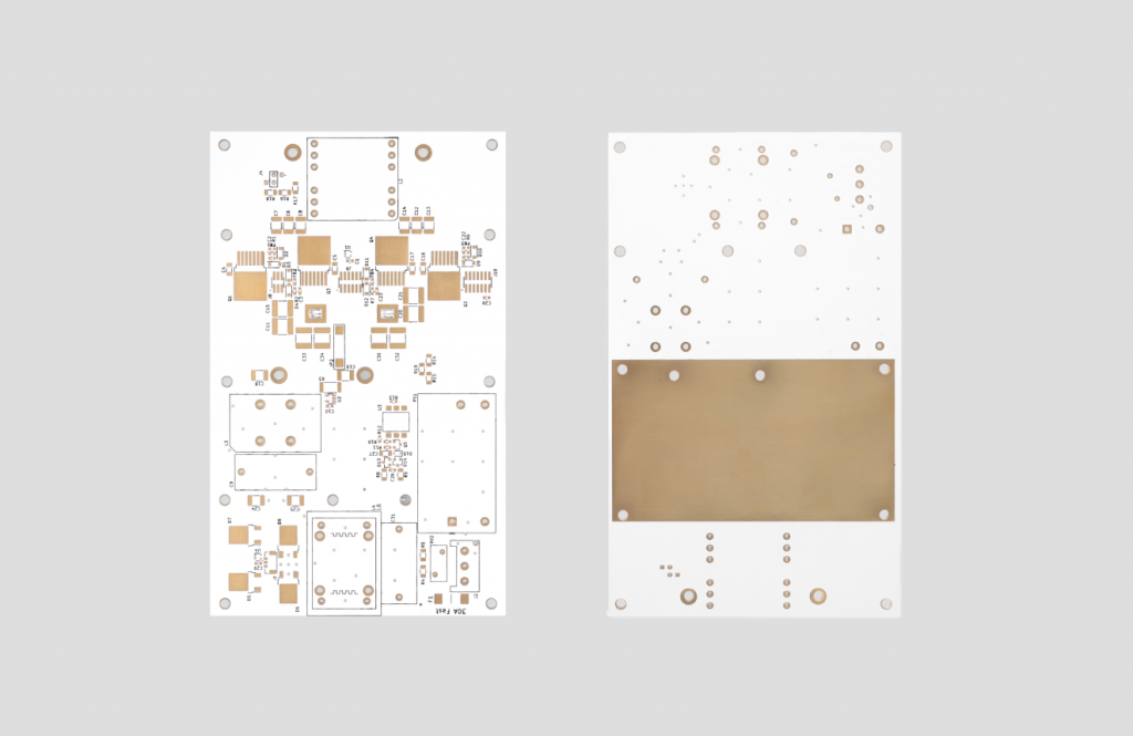
A 4-Lather MCPCB (Metal Core Printed Circuit Board) is a multilayer circuit board with superior thermal management capabilities, displaying four conductive copper layers bound to aluminum or copper substrate. This structure includes the upper layer for components, two inner layers for the stomach, and the lower layer attached to the metal core through the thermal conductive dielectric material.
This design efficiently transferring heat from the power component (such as high intensity LEDs) through the dielectric layer into the base of the metal, preventing excessive heat while maintaining electrical insulation. Multilayer configuration allows complex circuit design while the metal substrate increases mechanical stability and heat dissipation (usually 8-10x is better than a standard PCB).
What is stacked of 4 layers of MCPCB?
Stack-up a 4-Lather MCPCB:
- The top signal layer ‘ -The outer copper layer (usually thick 35-280îîiefing) for the installation of components and stomach high-speed signals, functioning as the surface of the primary circuit connection.
- First Inner Layerâ € œThe -Usually configured as a land field (GND) to provide electromagnetic protectors and low impedance return pathways for signals, while helping heat distribution.
- Second Inner Layerâ € œThe – Designed as a power plane (VCC) to provide a stable voltage distribution throughout the board, separated from the field of land with dielectric material.
- Base metal layer ‘ -Aluminum or copper substrate (thickness 1.0-5.0mm) which is bound to the lower layer through the thermal conductive dielectric (1.0-3.0 W/MK), acts as a media of primary heat dissipation.
What is the thickness of 4 layers of MCPCB?
- Overall thickness of the board ‘:: The standard range is 1.0 mm to 3.0 mm, with the most common 1.6 mm. The thinner option (0.8 mm to 1.2 mm) for compact design, a thicker version (2.0 mm to 3.0 mm) for high power application. Manufacturing tolerance is ± 0.1 mm for boards under 1.0 mm, â ± 10% for thicker boards.
- The thickness of the copper layer ‘:: Each conductive layer measures 35 îief to 280 îiefm (0.5 oz to 4 oz). The inner and extraordinary layers are suitable for uniform current distribution. Thicker copper (2 ounces to 4 ounces) increases the current capacity but can limit the smooth stomach.
- Metal core thicknessâ € œ:: Aluminum or copper substrate ranges from 1.0 mm to 5.0 mm. The standard thickness is 1.0 mm to 2.0 mm for optimal heat dissipation and weight balance.
- The thickness of the dielectric layer ‘:: The thermal conductive insulation layer is usually 50 îief to 150 îiefm thick, with thermal conductivity of 1.0 W/MK to 3.0 W/MK. Designed for efficient heat transfer while maintaining electrical insulation.
- Layer symmetryâ € œ:: Stack-up maintains mirror symmetry to prevent warping during thermal cycling and ensure structural stability.
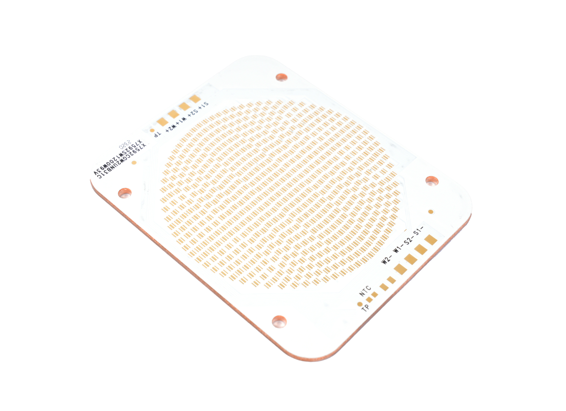
Why choose 4 MCPCB layers for UVC LEDs?
- Superior thermal management ‘:: MCPCBS efficiently eliminates heat through its metal core, maintains the performance of UVC LEDs and extending life.
- Power of power added power “:: The metal substrate prevents warping below high temperatures, ensuring reliability in UVC applications.
- Better performance consistencyâ € œ:: Effective heat dissipation stabilizes light output, important for UVC sterilization accuracy.
- Compatibility of compact design ‘:: Allows the LED layout with high density without thermal compromise, ideal for modules that are limited by space.
- Long -term reliability “: Reducing thermal voltage at the solder connection, minimizing the risk of failure in sustainable operations.
- Electric insulation ‘:: The dielectric layer prevents short circuits while maintaining efficient heat transfer.
- Industrial Standard Compliance ‘:: Meet security and reliability requirements for high power UVC LED systems.
How to optimize the thermal pathway 4 MCPCB layers for UVC LEDs?
- Selection of Metal Core Materials: Copper substrate (thermal conductivity 380-400 W/Mâ · K) with a thickness of 1.5-3.0mm is preferred to match the requirements of the high power density of UVC LED.
- Reduction of the thickness of the insulation layer: Low thermal resistance ceramics are used to fill the isolation layer, and thickness is controlled at 50-100îîlen to reduce thermal resistance between the metal nucleus and copper circuit.
- Thermal through strengthening: The thermal VIAS is 0.3-0.5mm in diameter arranged in a solid under the LED, and conductive glue is filled in to improve the efficiency of vertical thermal conductivity.
- Optimization of component layout: Forced alignment of LED and metal core areas to avoid the concentration of heat sources and reserves of heat -based expansion space.
- External heat dissipation relationship: The metal nucleus and external heat sink are connected through a high thermal conductivity team (such as graphite pads) to form an active-pile composite heat dissipation link.
How can 4 MCPCB layers increase the efficiency of UVC LED lighting?
Direct thermal path
- MCPCB four layers use a special copper layer to channel heat from UVC LEDs. This structure reduces thermal resistance to 30 € “50% compared to a single layer board, maintaining the temperature of the 15 €” 20 ° C crossing temperature during surgery.
Balanced power routing
- Separate coastal distributes currents evenly throughout the LED array, prevent hotspots. The test shows an increase of 10% 12% in wavelength stability in high drive conditions.
Isolation integrity
- The dielectric layer between the copper plane provides 5 kV electrical insulation. This prevents curved in a high -voltage UVC system while maintaining the clarity of signals for the control circuit.
EMI Mitigation
- Isolated power and soil aircraft reduces electromagnetic noise by 40â € “60 dB. It is important for medical sterilization equipment that requires communication free sensors.
Compact high power design
- The thermal layer allows the drive current up to 1,500 mA per LED without degradation. Allows 2x higher lumen density in applications that are limited to space such as portable disinfection units.
Mechanical endurance
- Multi-layer construction is curved under thermal pressure. Laboratory tests show 50% less soldering joint fatigue after 10,000 thermal cycles, ideal for outdoor UVGI systems.
Special Application Customization
- The layer can be allocated for thermal management, power trail, or RF protector. Activating optimization for scenarios such as water treatment in UV (prioritizing heat dissipation) or dynamic lighting (focusing on signal integrity).
How do 4 MCPCB layers for UVC LEDs reduce the risk of thermal escape?
- Thermal conductivity of the high efficiency of the metal substrate: Aluminum or copper is used as a basic ingredient, and thermal conductivity is much higher than the traditional FR4 board (aluminum is around 237 W/Mâ · K, copper of around 401 W/Mâ · K), which can quickly transfer heat produced by UVC LEDs from the Chip intersection area to the substrate to avoid excessive local temperatures.
- Low thermal resistance insulation layer design: The thin layer of high-performing isolation media (such as polymers filled with ceramics) is embedded between metal substrates and copper circuit layers, and its thickness is controlled at 50-100îîief
- Thermal diffusion effects of multi-layer copper layers: The circuit layer uses 1-2 oz copper foil (around 35-70îief), and heat diffusion tissue is formed through a large area copper coating design, which spreads heat concentrated in the LED area horizontally to the entire surface of the PCB, reducing the density of heat sources.
- Thermal layout through a dense array: Coated copper through a hole with a diameter of 0.3-0.5 mm is arranged below and around the LED package, with a distance of 1-2 mm to form a vertical heat conduction channel, directly connecting the upper circuit layer and metal substrate, shortening the heat conduction path.
- Rigid structure prevents thermal deformation: The high stiffness of the metal substrate (aluminum Young modulus is around 70 GPA) can effectively inhibit the bending or delamination of PCB at high temperatures, ensuring that the substrate of LED and heat discipline in close contact, avoiding the accumulation of heat caused by poor contact.
Conclusion
In conclusion, MCPCB 4-Lapis provides extraordinary thermal management solutions for UVC LED applications through the accumulation of optimized layers, efficient heat dissipation pathways, and balanced copper distribution. This board significantly increases lighting efficiency, prevents thermal escape, and extends LED life while maintaining cost effectiveness. For superior UVC LED performance, the 4-lapi MCPCB structure is proven to be very necessary with sophisticated thermal conductivity and stable operations under high power conditions. To implement this latest thermal solution in your UVC LED project, contact the best technology for competitive quotes and expert technical support: [email protected].
Tags: 4 MCPCB layers, 4 MCPCB layers for UVC LEDs
This entry was posted on Friday, July 4, 2025 at 18:59 and submitted under the best PCB, BestTPCB, MCPCB, Metal Core PCB. You can follow any response to this entry through RSS 2.0 bait. You can leave a response, or trackback from your own site.
Game Center
Game News
Review Film
Berita Olahraga
Lowongan Kerja
Berita Terkini
Berita Terbaru
Berita Teknologi
Seputar Teknologi
Berita Politik
Resep Masakan
Pendidikan
Berita Terkini
Berita Terkini
Berita Terkini
review anime
Gaming Center
Originally posted 2025-07-04 13:38:37.