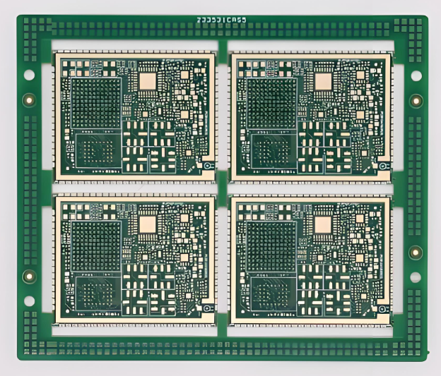
What is High Density Interconnect PCB?
High Density Interconnect PCB refers to a multilayer structure that uses laser microvias, thin dielectric layers and sequential lamination to increase routing density and improve electrical performance. Rather than routing signals through long mechanical vias, HDI stack designs focus on short vertical transitions between adjacent layers. This reduces inductance, improves impedance control, and allows smooth tone BGA output without increasing board size.
HDI electrical parameters commonly used in engineering documentation include:
- Line width/spacing: 60–75 µm (advanced builds can reach 40 µm)
- Microvia finished hole: 75–100 µm
- HDI interlayer dielectric thickness: 40–80 µm
- Copper thickness: outer HDI layer 12–18 µm, inner layer 18–35 µm
The HDI stack design emphasizes the proximity of the signal reference plane. The short dielectric distance lowers the loop inductance and stabilizes the return path, which is important in AI servers and high-speed computing boards.
High Density Interconnect PCB
When Should You Choose an HDI PCB Over a Standard Multilayer PCB for an AI Server or High-Speed System?
HDI becomes important when routing density or electrical requirements exceed the capabilities of conventional PCBs. AI server motherboards, accelerator modules, and edge computing boards often adopt HDI as the number of processor pins and high-speed channels increases dramatically.
Engineering decision indicators:
- BGA Pitch ≤ 0.5mm
- High-speed links above 10–25 Gbps
- Large processor or FPGA packages exceed 1000 pins
- Board size limitations require a compact layout
- Power distribution networks require a dense decoupling arrangement
In AI server designs, HDI is reduced through stubs and shortens differential pair transitions. This helps maintain the insertion loss budget and improves eye chart margins during high frequency operation.
How Do 1+N+1 and 2+N+2 HDI Stackup Design Strategies Affect Routing Density and Manufacturing Risk?
HDI Stackup Design Comparison Table
| Stacking Type | Typical Microvia Depth | Routing Density | Lamination Cycle | Application Example |
| 1+T+1 | L1-L2 / L(n-1)-Ln | Currently | 2 cycles | Robotics controller, embedded CPU board |
| 2+N+2 | stack L1-L2-L3 | Tall | 4 cycles | AI server computing module |
| 3+T+3 | Multi-stack microvia | Very high | 6+ cycles | Advanced telecommunications or HPC |
More stacking layers increases routing flexibility but also introduces additional lamination cycles. Engineers often start with 1+N+1 and evaluate whether further buildup layers are needed based on the BGA removal results.
HDI Microvia Engineering Parameters Table
| Parameter | Recommended Range | Engineering Impact |
| Laser Through Diameter | 75–100 microns | Routing density and coating reliability |
| Catch Pad Size | 150–250 microns | Circular ring control |
| Aspect Ratio | ≤ 0.8:1 | Prevents coating voids |
| Through Structure | Staggered is preferred | Improves thermal reliability |
| Copper Content Thickness | cap 15–25 µm | Required for via-in-pad |
Microvia planning should begin during stack definition because structural changes will later require redesign of much of the layout.
When Will Via-in-Pad Become Mandatory in Fine-Pitch HDI PCB and AI Server BGA Fanout?
Via-in-pad is used when the routing channels around the BGA pad are insufficient. In AI server processors or high-density networking ASICs, pad pitch often forces vertical signal output.
Engineering scenarios where VIP is justified:
- 0.4 mm pitch GPU package or AI accelerator
- A high-speed differential pair that requires the shortest path
- Dense decoupling network beneath the core voltage rail
VIP pads require copper-filled microvias, planarization to maintain flatness, and careful solder mask design.
How Does HDI PCB Compare to Standard PCB in Signal Integrity, Size Reduction, and Layer Utilization?
| Engineering Metrics | HDI PCB | Standard PCB |
| Through Stub Length | Very short | Long unless drilled to the back |
| Routing Channel Density | Tall | Limited |
| Loop Inductance | Lower | Higher |
| Council Area | Reduced | Bigger |
| Coating Efficiency | High utilization | Lower utilization |
| EMI Performance | Improved due to compact loop | Depends on the layout strategy |
Shorter vertical transitions on HDI improve signal margins in high-frequency environments such as AI servers.
What is the actual HDI fabrication flow and which process steps most influence the results?
HDI Fabrication Process Table
| Stepping | Control Key Parameters | Risk Areas |
| Core Lamination | Thickness tolerance ±10 µm | curved page |
| Stacking Laminate | Resin flow uniformity | Empty formation |
| Laser Drilling | Positioning accuracy ±20 µm | Through misalignment |
| Copper Plating | Current density control | Microvia Reliability |
| Imaging & Etching | Line width tolerance ±10 µm | Signal impedance shift |
Uniformity of microvia coating and control of dielectric thickness are major contributors to HDI production yield.
Which Material is Preferred for HDI Stack Design in AI Server PCBs and High-Speed Applications?
| Material Category | Range Dk | Df range | Typical Use |
| FR-4 Tg is high | 3.8–4.2 | 0.015–0.018 | General HDI board |
| Low Loss Laminate | 3.2–3.6 | 0.004–0.009 | AI servers and networks |
| RCC Thin Dielectric | ~3.5 | 0.01 | Layer buildup |
Material selection must be aligned with electrical performance targets and thermal cycling conditions during assembly.
How Do Engineers Route Fine-Pitch BGAs on HDI PCBs Without Signal Integrity Issues or Rework Risk?
Routing strategies start with stack planning, not drawing traces. Engineers typically follow a structured workflow:
- Set a ground reference layer adjacent to the signal layer
- Exit the first BGA row using microvia to the inner routing layer
- Maintain differential pair distance within controlled tolerances
- Avoid excessive layer transitions that create impedance discontinuities
Commonly used HDI differential routing parameters in AI server layout:
- Pair distance: 100–150 µm
- Trace width: 65–80 µm
- Reference plane distance: 60 µm
How Can You Improve HDI PCB Reliability Against CAF, Microvia Fatigue, and Warpage?
| Failure Mechanism | Root Cause | Engineering Control |
| CAF growth | Humidity + voltage bias | Increase conductor spacing |
| Microvia Fatigue | CTE mismatch | Use staggered microvia |
| curved page | Copper imbalance | Symmetrical copper distribution |
Balanced copper distribution across layers significantly improves long-term reliability in high-power computing environments.
What Drives HDI PCB Costs and How Does a Detailed Breakdown of HDI Costs Help Technical Decisions?
HDI Cost Breakdown Engineering Table
| Cost Drivers | Process Impact | Cost Effects |
| Sequential Lamination | Additional layer of buildup | Tall |
| Laser Microvia Drilling | Equipment time | Medium-High |
| VIP Contains Copper | Extra layering step | Currently |
| Fine Line Imaging | Strict tolerance control | Currently |
| Low Loss Material | Premium materials | Variable |
Understanding the breakdown of HDI costs allows engineers to optimize stack designs early and avoid unnecessary process steps.
Why Choose EBest as Your High Density Interconnect PCB Manufacturer?
If you move to an HDI PCB project, your biggest risk will not be the CAD work. This is a misalignment between design intent and fabrication reality. EBest Circuit positions itself as a one-stop PCBA service provider that better understand technician needs, so your stack, microvia and assembly choices remain consistent from quote to delivery.
- DFM is free and processing adaptation suggestions before release
- 20 years portion 1800+ customers And 10,000+ engineers
- One Stop Service: PCB, components, PCBA, testing, and box manufacturing
- No MOQ with personal service for prototypes and small batches
- ISO9001/ISO13485, IATF16949, AS9100D quality system support
- MES & traceability for process tracking and accountability
- Fast PCBA delivery 1.5 weeks options for urgent programs
- Before and after sales technical support, with fast feedback (often within 12 hours)
- Prototypes & small volumes accepted, with fast turnaround and focus on on-time delivery
- High quality building, special requests available, supported by a strong R&D team
FAQs
1. What BGA pitches do HDI stack designs typically require?
HDI stack designs are usually chosen when the BGA pitch approaches 0.5 mm because routing density becomes limited using only mechanical vias.
2. Is 2+N+2 always necessary for AI HDI PCB servers?
Many AI server boards start with a 1+N+1 structure and only move to 2+N+2 when routing density requires an additional build-up layer.
3. Are stacked microvias reliable for high power systems?
Stacked microvias are reliable if the copper filling and plating thickness are well controlled, although a staggered structure often increases durability.
4. Does HDI PCB always reduce the total number of layers?
HDI improves routing efficiency and signal integrity but does not necessarily reduce the total number of layers.
5. How early should HDI stack design be completed?
Stack definition must be performed before deployment and routing to prevent redesign cycles.
Tags: hdi pcb design guide, hdi pcb manufacturers, hdi stack, hdi technology, high density interconnect pcb
This entry was posted on Saturday, February 28, 2026 at 10:05 am and is filed under best PCB, best PCB, Design Guide, FAQ, HDI PCB. You can follow any responses to this entry via the RSS 2.0 feed. You can skip to the end and leave a response. Ping is currently not allowed.
Berita Terkini
Berita Terbaru
Daftar Terbaru
News
Jasa Impor China
Berita Terbaru
Flash News
RuangJP
Pemilu
Berita Terkini
Prediksi Bola
Technology
Otomotif
Berita Terbaru
Teknologi
Berita terkini
Berita Pemilu
Berita Teknologi
Hiburan
master Slote
Berita Terkini
Pendidikan
Resep
Jasa Backlink
Slot gacor terpercaya
Anime Batch