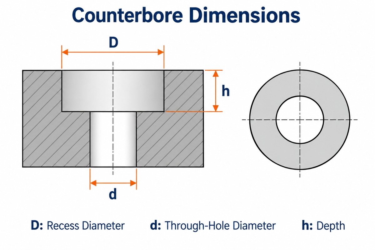
A counterbore is a cylindrical, flat-bottomed recess around a smaller hole. It provides space for a screw head, washer or other hardware to sit below the surrounding surface. A drawing must define the smaller hole diameter, recess diameter and recess depth; the screw thread size alone is not enough.
On a PCB, the recess also removes insulating material and may approach internal copper. The design therefore needs a remaining-thickness calculation as well as a fastener-fit check. A counterbore that fits a metal bracket can be too deep for the circuit board mounted beside it.
Key Takeaways
- A counterbore has straight walls and a flat bearing floor; a countersink has a conical seat.
- The ⌴ symbol identifies a counterbore. Diameter, depth, machining side and tolerances make the feature manufacturable.
- Choose recess dimensions from the actual screw head and washer, not just the nominal thread size.
- An ordinary M3 socket-head cap screw can have a 3 mm head height, so it cannot be fully recessed into a 1.6 mm PCB.
- Check minimum board thickness minus maximum recess depth, then review the remaining structure and internal copper.
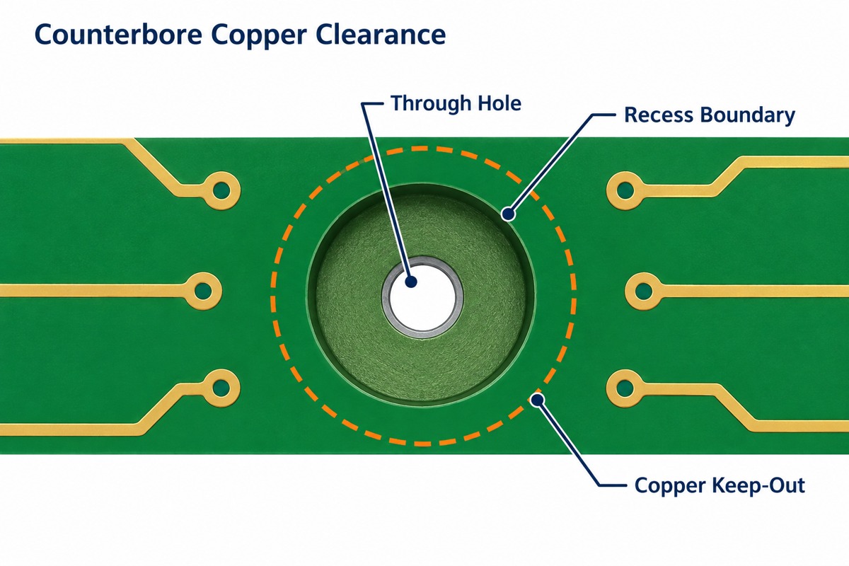
- Copper clearance follows the full recess boundary, not only the smaller through hole.
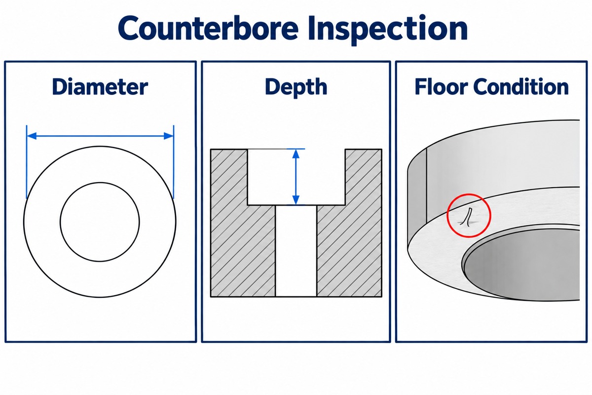
- Inspection should check diameter, depth, location, floor condition and hardware fit.
What Is a Counterbore Hole?
A counterbore hole is a stepped hole with a larger cylindrical opening above a smaller bore. The annular floor supports the underside of the fastener head or washer, while the smaller bore provides a path for the screw shank.
| Feature | Geometry | Primary purpose |
| Counterbore | Cylindrical recess with a flat floor | Accommodate a cylindrical head or washer |
| Countersink | Conical recess | Seat a matching flat-head screw |
| Spotface | Shallow machined flat seat | Create a suitable bearing surface |
| Clearance hole | Single-diameter bore | Allow the screw shank to pass without thread engagement |
The word also names the cutting tool used to make this recess. A request for a “counterbore” should therefore distinguish the finished feature from the tool. The smaller hole can be through or blind, although PCB mounting designs commonly use a through hole.
When Does a PCB Need a Counterbore?
A PCB needs a counterbore when hardware must sit below its surface and the board has enough material to retain a sound bearing floor. Examples include a recessed mounting screw near an enclosure wall or hardware that would otherwise interfere with a cover.
At EBest Circuit, we support counterbore-hole designs within our FR4 PCB fabrication services. Send the screw drawing and board stackup with the mechanical detail so we can review the machining side, remaining material and copper clearances before production.
Recessing a screw does not automatically make its joint stronger. Where the board is too thin, move the recess into the enclosure or mounting bracket, or use a suitable standoff. Our earlier article on counterbores in PCB design and manufacturing introduces related mounting applications.
Counterbore Symbol and Drawing Callout
The counterbore symbol is ⌴, placed before the recess diameter. A complete counterbore callout also identifies depth and the smaller hole, with units and tolerances supplied by the detail or drawing notes.
For example, an illustrative drawing could specify 4X Ø3.4 THRU; ⌴ Ø6.5, DEPTH 3.2; TOP SIDE; ALL DIMENSIONS IN mm. This describes four through holes, each with a larger top-side recess. It is a reading example, not an approved PCB design or a universal M3 standard.
- 4X: four identical features.
- Ø3.4 THRU: the smaller bore passes through the part.
- ⌴ Ø6.5: the cylindrical recess is 6.5 mm in diameter.
- DEPTH 3.2: the recess floor lies 3.2 mm below the specified top reference surface.
- TOP SIDE: the feature is machined from the identified face.
Add dimensional tolerances, hole location and the intended plated or non-plated condition before releasing the drawing. A simple “M3 counterbore” note leaves the screw family, washer and recess geometry unresolved. If a font does not display ⌴ clearly, retain the section view and use an explicit COUNTERBORE note.
How Do You Choose Counterbore Diameter and Depth?
Choose the diameter to clear the maximum screw-head or washer diameter, and choose the depth to achieve the required installed head position. Check these dimensions against the purchased fastener drawing, including its tolerances.
A standard-height M3 socket-head cap screw commonly has a 5.5 mm head diameter and a 3 mm head height. These are fastener dimensions, not the finished recess dimensions. A low-head or button-head M3 screw has a different envelope, even though its thread is still M3.
- Radial fit: the smallest permitted recess must clear the largest permitted head, allowing for positional error.
- Axial fit: the shallowest permitted recess must accommodate the tallest head and any washer when full recessing is required.
- Tool access: allow the driver or socket to reach the screw without hitting nearby components.
- Corner fit: check the under-head fillet against the smaller hole edge and any specified edge break.
For an illustrative 6.5 mm recess and 5.5 mm head, nominal radial clearance is (6.5 − 5.5) ÷ 2 = 0.5 mm per side. Tolerances and offset reduce that clearance. Do not treat a nominal fit as a worst-case fit, or add a washer after approving the recess depth.
How Much PCB Thickness Must Remain Below the Recess?
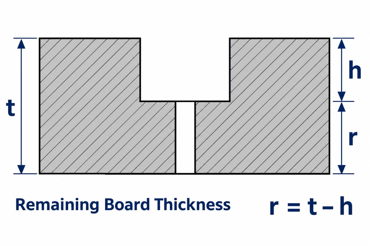
The worst-case remaining thickness is the minimum finished board thickness minus the maximum recess depth. That result must still satisfy the mechanical load and electrical-isolation requirements of the actual stackup.
Remaining thickness = minimum finished thickness − maximum machined depth. There is no single remaining-thickness value that is safe for every laminate, fastener load and copper arrangement.
| Illustrative input | Value |
| Board thickness specification | 3.20 ± 0.15 mm |
| Recess depth specification | 1.00 ± 0.10 mm |
| Minimum finished thickness | 3.05 mm |
| Maximum recess depth | 1.10 mm |
| Worst-case remaining thickness | 1.95 mm |
These inputs demonstrate the calculation; they are not EBest Circuit capability limits or a released fastening design. The 1.95 mm result says how much material remains, not whether the joint passes its strength or insulation requirements.
A 3 mm-high screw head cannot be fully buried in a 1.6 mm board while retaining a floor. Increasing recess diameter does not solve this depth problem. Change the hardware or move the recessed feature to a thicker mechanical part.
How Should Copper Be Cleared Around a Counterbore?
Clear copper from the entire machined recess envelope on every layer the cut can reach, then add the project’s manufacturing and electrical clearance allowances. A keep-out around only the smaller through hole can leave copper exposed on the recess wall or floor.
Review the stackup in section, not just the top-layer layout. Include recess position and diameter tolerances, depth variation, internal-plane registration and the conductive hardware envelope. Solder mask should not be treated as the sole insulation between a clamped screw and a conductor.
- Check internal planes as well as visible surface traces.
- Define whether any copper contact is intentional for chassis grounding.
- Keep nearby vias, pads and components outside the required machining and assembly envelope.
- For metal-core boards, assess isolation from the exposed metal base separately.
The final clearance belongs in the approved design rules and fabrication drawing. Our PCB design guidance provides the broader design context; the recessed mounting detail still needs a project-specific stackup review.
Which Counterbore Tool Creates a Flat Bottom?
A purpose-made counterbore cutter or a suitable flat-bottom milling tool can form the recess. An ordinary pointed twist drill leaves a conical bottom and does not create the required flat annular bearing seat by itself.
A piloted counterbore tool uses the smaller hole to guide the cutter. CNC milling can instead locate the recess from the board’s reference system. Tool choice depends on material, diameter, depth, access and the required floor finish; metalworking speed-and-feed charts should not be copied directly to glass-reinforced PCB laminate.
For FR4, the process must address abrasive glass reinforcement, breakout and dust extraction. The fabrication drawing should specify the finished geometry and acceptance requirements, while the manufacturer selects a qualified machining method.
How Are Counterbores Made in PCBs?
PCB counterbores are made by controlled-depth machining at the specified hole locations, followed by cleaning and dimensional inspection. The fabricator determines the operation sequence relative to drilling, plating and other board processes.
- Review the detail: reconcile the mechanical drawing, stackup, drill data and fastener envelope.
- Establish the reference: identify the machining side, depth datum and location datum.
- Support the board: fixture the part so cutting loads do not bend or damage it.
- Machine the feature: control the larger recess diameter and floor depth using the approved toolpath.
- Clean and inspect: remove debris, check edges and measure the finished feature.
If the smaller bore must be plated, specify that requirement independently from the recess surfaces. Machining after plating can remove copper in the cut area; a drawing that merely says “plated hole” does not define the finished condition of every exposed surface.
What Should Counterbore Inspection Check?
Inspection should verify recess diameter, depth, location and floor condition, then confirm that the specified hardware seats correctly. A screw fitting into the hole does not prove that sufficient laminate or copper clearance remains.
| Feature | Inspection approach |
| Diameter and relative position | Optical or dimensional measurement against drawing datums |
| Recess depth | Depth measurement from the specified surface to the annular floor |
| Floor and edges | Magnified inspection for burrs, raised fibers, damage and uneven seating |
| Fastener fit | Specified screw and washer checked for interference and installed height |
| Hidden layer relationship | Stackup review; agreed sectioning or additional verification where needed |
A depth-gauge probe must contact the recess floor, not fall into the central through hole. Agree the measurement method before production when the annular seat is narrow or the top surface has features that affect the reference.
What Causes Counterbore Assembly Problems?
Incorrect depth, insufficient diameter, hole offset and damaged bearing surfaces are common causes of poor seating. Identify the physical interference before enlarging or deepening the recess.
- Head stands proud: check actual head height, washer thickness and shallowest recess depth.
- Screw enters but will not seat: check the under-head fillet, burrs and small-hole edge geometry.
- Head rubs one side: check positional offset and minimum radial clearance.
- Board cracks during tightening: review remaining thickness, backing support and the assembly torque specification.
- Electrical contact appears after assembly: inspect exposed copper, metal-core contact and the hardware clearance envelope.
Do not correct a seating problem by tightening harder. Rework that changes recess depth or exposes a new layer needs engineering approval and renewed inspection.
When Is a Countersink or Spotface More Appropriate?
A countersink is appropriate for a matching conical flat-head screw; a spotface is appropriate when only a flat bearing surface is needed. Neither is a universal replacement for a counterbore in a thin PCB.
A countersink still removes material and must match the screw’s included angle. A spotface normally leaves the head above the surrounding surface, so it will not solve a requirement for full head recessing. For a wider comparison of the hole types and hardware, see our counterbore vs countersink guide.
FAQ About Counterbores
Does counterbore depth include the through hole?
No. It measures from the specified entry surface to the floor of the larger recess. Through-hole depth or the THRU designation is a separate requirement.
Is a counterbore hole threaded?
The enlarged recess normally provides clearance for hardware, not thread engagement. A smaller bore may be threaded in a mechanical component, but ordinary PCB mounting holes usually pass the screw to a nut, standoff or threaded enclosure.
Can the same counterbore fit every M3 screw?
No. M3 identifies the nominal thread diameter, not one head shape or height. Socket-head, low-head and button-head screws require different envelope checks. Washers can also change the required diameter and depth.
Is counterboring the same as backdrilling a PCB?
No. Counterboring creates a mechanical recess, usually for hardware. PCB backdrilling removes an unwanted plated via stub for electrical performance. Their purposes, depth targets and acceptance criteria are different.
Are Gerber files enough to specify a counterbore?
Not reliably on their own. Provide a dimensioned mechanical drawing with a section view, depth, machining side and tolerances, together with drill data and the stackup. Reconcile any differences between the drawing and manufacturing files before release.
Need a PCB Counterbore Reviewed Before Fabrication?
At EBest Circuit, we can review the recessed-hole detail alongside your FR4 board design and manufacturing files. Our PCB and PCB assembly services let you address fabrication geometry and final hardware access within the same project.
Send Gerber files, drill data, the board stackup, a dimensioned counterbore drawing, the screw or washer specification and quantities to [email protected]. Include any insulation, grounding or mechanical-load requirements so we can assess the feature before quoting.
You may also like






Tags: counterbore, counterbore callout, counterbore hole, counterbore symbol, counterbore tool
PakarPBN
A Private Blog Network (PBN) is a collection of websites that are controlled by a single individual or organization and used primarily to build backlinks to a “money site” in order to influence its ranking in search engines such as Google. The core idea behind a PBN is based on the importance of backlinks in Google’s ranking algorithm. Since Google views backlinks as signals of authority and trust, some website owners attempt to artificially create these signals through a controlled network of sites.
In a typical PBN setup, the owner acquires expired or aged domains that already have existing authority, backlinks, and history. These domains are rebuilt with new content and hosted separately, often using different IP addresses, hosting providers, themes, and ownership details to make them appear unrelated. Within the content published on these sites, links are strategically placed that point to the main website the owner wants to rank higher. By doing this, the owner attempts to pass link equity (also known as “link juice”) from the PBN sites to the target website.
The purpose of a PBN is to give the impression that the target website is naturally earning links from multiple independent sources. If done effectively, this can temporarily improve keyword rankings, increase organic visibility, and drive more traffic from search results.
