When designing LED circuits, many professionals struggle with selecting the right current limiting resistor to protect LEDs and ensure stable performance, but what exactly is a current limiting resistor and how do you choose the correct one for your LED application? This blog breaks down every critical detail, from definitions and working principles to calculation methods and practical selection tips, addressing common pain points and providing actionable guidance to help you avoid costly mistakes and build reliable circuits.
What is a Current Limiting Resistor?
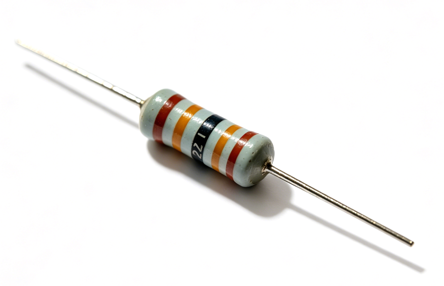
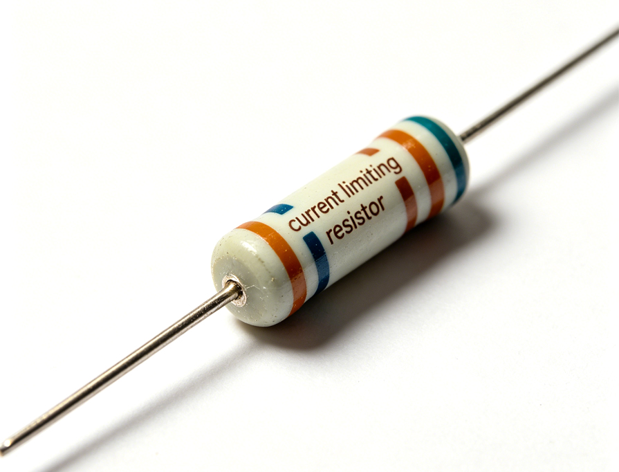
A current limiting resistor is a passive two-terminal electronic component designed to control the amount of electric current flowing through a circuit. It restricts current to a safe, predetermined level by introducing a specific amount of electrical resistance, preventing excessive current that could damage sensitive components like LEDs.
Also known as a limiting resistor, it operates based on Ohm’s Law, converting excess electrical energy into heat that dissipates safely into the surrounding environment. Unlike other resistors, its primary function is not just to adjust signal levels or divide voltage but to act as a protective barrier.
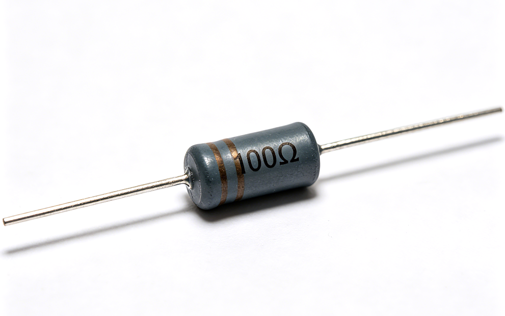
It is available in various forms, including carbon film, metal film, and wire wound, each suited to different current and power requirements. The key distinction lies in its application: it is specifically sized to limit current rather than serve general circuit tuning purposes.
What is the Symbol of Current Limiting Resistors?
Current limiting resistors use the same standard symbols as all fixed resistors, as their function is a specific application of general resistor technology. Two primary symbols are used globally, aligned with international standards.
The ANSI style symbol features a rectangular box with two leads extending from either side, representing the resistor’s body and connection points.
The IEC symbol, more commonly used in European and global circuits, is a simple zigzag line with leads on both ends, visually depicting the resistance path that restricts current flow.
These symbols are identical for all fixed resistors because the current limiting function is determined by the resistor’s value and placement in the circuit, not its physical design or symbol. When reading schematics, look for either symbol in series with an LED to identify the component responsible for current control.
What is the Purpose of a Current Limiting Resistor?
The core purpose of a current limiting resistor is to restrict electrical current to a safe level for the components in a circuit. It prevents overcurrent conditions that can cause overheating, component failure, or permanent damage.
For sensitive components like LEDs, this protection is critical, as they have strict current tolerances that, when exceeded, lead to immediate burnout. Beyond protection, it stabilizes circuit performance.
It ensures consistent current flow even when there are minor fluctuations in input voltage, maintaining uniform brightness in LEDs and preventing erratic behavior. It also absorbs excess voltage in circuits where the power supply voltage exceeds the component’s required operating voltage, converting the excess into heat to keep the circuit within safe parameters.
Additionally, it acts as a simple, cost-effective short circuit protection mechanism. In the event of a component short, the limiting resistor restricts the maximum current in the circuit, protecting the power supply and other components from damage.
How Does a Current Limiting Resistor Work?
A current limiting resistor works by leveraging Ohm’s Law, which states that current (I) is equal to voltage (V) divided by resistance (R), or I = V/R. When connected in series with an LED or other component, it increases the total resistance of the circuit, thereby reducing the total current flowing through the loop.
In a typical LED circuit, the power supply provides a fixed voltage, while the LED has a specific forward voltage drop, the voltage required to turn it on. The current limiting resistor is sized to absorb the difference between the supply voltage and the LED’s forward voltage, restricting the current to the LED’s safe operating level.
For example, if a 5V power supply is used with an LED that has a 2V forward voltage drop, the resistor absorbs the remaining 3V. By selecting the correct resistance value, the current is limited to the LED’s rated level, typically 10 to 20mA for standard LEDs. The resistor dissipates the excess energy as heat, which is why power rating is a critical consideration when selecting the component.
When to Use a Current Limiting Resistor?
A current limiting resistor is essential in specific circuit scenarios where components are at risk of overcurrent damage or performance instability. Below are the key scenarios where you should use a current limiting resistor, organized into clear, actionable points:
- When connecting components with strict current tolerances to a high-current power supply – Use a current limiting resistor whenever the power supply can provide more current than the component can safely handle. The most common application is with LEDs, but it also applies to other sensitive components like diodes, transistors, and some integrated circuits (ICs) that have fixed maximum current ratings.
- When the power supply voltage exceeds the component’s forward or operating voltage – This is a mandatory use case. If the power supply voltage is higher than the component’s required operating voltage (e.g., a 5V supply connected to an LED with a 2V forward voltage drop), the resistor absorbs the excess voltage and restricts current, preventing the component from drawing too much current and burning out.
- When circuit voltage is prone to fluctuations – If the input voltage of your circuit is not stable (e.g., battery-powered circuits where voltage drops over time, or AC-powered circuits with minor voltage spikes), a current limiting resistor stabilizes current flow. Even small voltage changes can cause significant current spikes in sensitive components, and the resistor mitigates this risk to ensure consistent performance.
- When short circuit protection is needed – Incorporate a current limiting resistor in circuits where short circuits could occur (e.g., loose connections, component failure). The resistor restricts the maximum current in the circuit during fault conditions, protecting the power supply and other components from damage, overheating, or permanent failure.
- When using low-voltage components with standard power supplies – Low-voltage components (e.g., small signal diodes, microcontrollers’ input pins) connected to standard power supplies (5V, 12V, 24V) require a current limiting resistor. These components cannot handle the full current from the power supply, so the resistor ensures current stays within their safe operating range.
Why LED Needs Current Limiting Resistor?
LEDs need a current limiting resistor because they have very low internal resistance and an exponential current-voltage relationship. Unlike incandescent bulbs, which have variable resistance that increases with temperature, LEDs have a fixed forward voltage drop.
They will draw excessive current if connected directly to a power supply, even if the supply voltage is only slightly higher than the LED’s forward voltage. LEDs have strict maximum current ratings, typically 10 to 30mA for standard 5mm LEDs and higher for high-power variants.
Exceeding this current causes the LED to overheat, degrade rapidly, and eventually burn out. The current limiting resistor ensures the current stays within this safe range, protecting the LED and extending its lifespan.
Additionally, LEDs have consistent forward voltage drops that vary by color and type. A current limiting resistor compensates for these variations and differences in power supply voltage, ensuring uniform current flow and consistent brightness across multiple LEDs in a circuit.
What Happens without Current Limiting Resistor LED?
Without a current limiting resistor, an LED will immediately draw excessive current when connected to a power supply with a voltage higher than its forward voltage drop. This leads to rapid overheating of the LED’s semiconductor junction, causing the LED to burn out within seconds or minutes, depending on the voltage and current levels.
In most cases, the LED will emit a bright flash before dimming and failing completely. The excessive current can also damage the power supply, especially in low-current power supplies that are not designed to handle short circuit or overcurrent conditions.
It may cause the power supply to shut down, overheat, or fail permanently. Even if the LED does not fail immediately, operating without a current limiting resistor significantly reduces its lifespan.
The LED will degrade faster, with brightness decreasing over time, and may develop internal damage that leads to inconsistent performance or sudden failure. In circuits with multiple LEDs, the lack of limiting resistors can cause uneven current distribution, resulting in some LEDs being brighter than others or failing at different rates.
How to Calculate Current Limiting Resistor for LED?
Calculating a current limiting resistor for an LED is straightforward using a simple formula derived from Ohm’s Law. The formula is R = (Vsource – Vf) / If, where:
– R is the resistance in ohms – Vsource is the power supply voltage – Vf is the LED’s forward voltage drop – If is the desired forward current in amps
Follow these steps to calculate the correct resistance value:
Step 1: Identify key parameters – Determine the power supply voltage (Vsource), which is typically 5V, 3.3V, or 12V. Find the LED’s forward voltage drop (Vf) and maximum forward current (If) from the LED’s datasheet.
Typical Vf values are 1.8–2.2V for red LEDs, 2.0–3.5V for green LEDs, and 3.0–3.6V for blue or white LEDs. Standard If values range from 10 to 20mA (0.01 to 0.02A) for most LEDs.
Step 2: Plug values into the formula – Subtract the LED’s Vf from the Vsource to get the voltage across the resistor. Divide this value by the desired If to get the required resistance.
For example, if Vsource is 5V, Vf is 2.1V (green LED), and If is 10mA (0.01A), the calculation is R = (5 – 2.1) / 0.01 = 290 ohms.
Step 3: Select a standard resistor value – Resistors are manufactured in standard values (E24 series). Choose the nearest standard value that is equal to or slightly higher than the calculated resistance to ensure current does not exceed the LED’s rating.
For the example above, 290 ohms is closest to the standard 300 ohm resistor.
Step 4: Calculate power rating – Ensure the resistor can handle the power it will dissipate. Use the formula P = I²R or P = (Vsource – Vf) × If.
For the example, P = (0.01)² × 300 = 0.03W. Select a resistor with a power rating at least twice the calculated value, typically 1/8W or 1/4W for standard LED circuits.
What Current Limiting Resistor Does a Green LED Need?
The current limiting resistor required for a green LED depends on three key factors: the power supply voltage, the green LED’s forward voltage drop, and the desired forward current.
Green LEDs have a typical forward voltage drop (Vf) of 2.0 to 3.5V, with most standard 5mm green LEDs having a Vf of 2.1 to 2.5V.
For a common 5V power supply and a standard green LED with a Vf of 2.1V and desired current (If) of 10mA (0.01A), the required resistance is calculated as R = (5 – 2.1) / 0.01 = 290 ohms. The nearest standard resistor value is 300 ohms, which is ideal for this application.
If using a 3.3V power supply with the same green LED (Vf = 2.1V, If = 10mA), the calculation becomes R = (3.3 – 2.1) / 0.01 = 120 ohms, which is a standard value.
For higher current requirements (e.g., 20mA), the resistance would be R = (5 – 2.1) / 0.02 = 145 ohms, with the nearest standard value being 150 ohms.
Always check the green LED’s datasheet for exact Vf and maximum If values, as these can vary by manufacturer and LED type. High-power green LEDs may require lower resistance values but higher power resistors to handle increased current and heat dissipation.
How to Choose Current Limiting Resistor for LED?
Choosing the right current limiting resistor for an LED is a systematic process that ensures the resistor effectively protects the LED and maintains stable circuit performance. Below are clear, actionable points to guide your selection:
1. Calculate the required resistance value first – Start with the core formula derived from Ohm’s Law: R = (Vsource – Vf) / If. Here, Vsource is your power supply voltage, Vf is the LED’s forward voltage drop, and If is the desired forward current (in amps). You can find the exact Vf and If values from the LED’s datasheet, as these parameters vary by LED color and type.
2. Select a standard resistor value – Resistors are manufactured in standard values (E24 series), so you won’t always find the exact calculated resistance. Choose the nearest standard value that is equal to or slightly higher than the calculated resistance. This ensures the current flowing through the LED does not exceed its safe rating, and it also extends the LED’s lifespan.
3. Verify the resistor’s power rating – The resistor dissipates excess energy as heat, so its power rating must be sufficient to handle this heat. Calculate the power dissipation using P = I²R or P = (Vsource – Vf) × If. For long-term reliability, select a resistor with a power rating at least twice the calculated value. For most standard LED circuits, 1/8W or 1/4W resistors are sufficient; high-power LEDs may require 1/2W or higher.
4. Consider the LED circuit configuration – If you’re using multiple LEDs in series, add all their Vf values together when calculating the required resistance. If LEDs are in parallel, each LED must have its own current limiting resistor to ensure even current distribution and prevent some LEDs from drawing more current than others.
5. Account for voltage fluctuations – If your circuit’s input voltage is prone to fluctuations, select a resistor with a tolerance of 5% or better. This helps maintain consistent current flow through the LED, avoiding brightness variations or potential damage caused by sudden current spikes.
6. Choose the appropriate resistor type – For most standard LED applications, affordable carbon film resistors (5% tolerance) work well. If you need more precise current control (e.g., in high-precision circuits), opt for metal film resistors, which offer better tolerance (1% or 2%). For high-power LED circuits, use wire wound resistors, which can dissipate more heat effectively.
How to Determine Resistor Size for Current Limiting?
Determining the resistor size for current limiting is a systematic process that ensures the resistor functions safely and effectively. The “size” here refers to two key aspects: resistance value (ohms) and power rating (watts), both of which are critical to avoid resistor failure and protect LED circuits. Follow these step-by-step instructions to determine the correct resistor size:
Step 1: Calculate the required resistance value – First, determine the resistance value needed to limit the current to the LED’s safe operating level. Use the formula R = (Vsource – Vf) / If, where Vsource is the power supply voltage, Vf is the LED’s forward voltage drop, and If is the desired forward current (in amps). This formula is derived from Ohm’s Law and ensures the resistor restricts current to a safe range, which is the core function of a current limiting resistor. You can find Vf and If values from the LED’s datasheet.
Step 2: Understand the relationship between resistance value and physical size – Note that the resistance value (ohms) does not directly determine the resistor’s physical dimensions. However, for standard through-hole resistors of the same power rating, lower resistance values (e.g., 100 ohms) are typically slightly smaller than higher resistance values (e.g., 10k ohms). This is a general observation and may vary by resistor type (e.g., carbon film vs. metal film).
Step 3: Calculate the required power rating – The power rating (watts) is the primary factor determining the resistor’s physical size, as it dictates how much heat the resistor can safely dissipate. Use the formula P = I²R or P = (Vsource – Vf) × If to calculate the power the resistor will dissipate. To ensure long-term reliability, select a resistor with a power rating at least twice the calculated value—this prevents overheating and premature failure.
Step 4: Match power rating to physical size – Choose a resistor physical size that matches the calculated power rating. Higher power ratings require larger resistors to dissipate more heat. For reference: a 1/8W resistor is small (ideal for low-power LED circuits), a 1/4W resistor is slightly larger, a 1/2W resistor is larger still, and 1W+ resistors are significantly bigger and better suited for high-power applications.
Step 5: Select the appropriate resistor type – Choose a resistor type based on the circuit’s power requirements and performance needs. Carbon film resistors are affordable and suitable for low-power LED circuits. Metal film resistors offer better tolerance and stability, making them ideal for circuits where current consistency is important. Wire wound resistors are designed for high-power applications, as they can dissipate more heat effectively.
Step 6: Ensure physical size fits the circuit layout – Finally, confirm that the selected resistor’s physical size fits your circuit design. Surface mount resistors are smaller and ideal for compact circuits, while through-hole resistors are larger but easier to prototype with and solder to breadboards or circuit boards.
How to Use a Current Limiting Resistor?
Using a current limiting resistor is simple, but proper placement and wiring are critical to ensure it protects the LED and functions correctly, this is because the resistor needs to effectively restrict current flow to the LED, as it is connected in series to limit the current in the circuit. Below are clear, step-by-step instructions to use a current limiting resistor correctly:
Step 1: Confirm the selected resistor parameters – Before wiring, double-check that the current limiting resistor matches the calculated specifications (resistance value and power rating). Ensure the resistor’s resistance is the standard value selected (equal to or slightly higher than the calculated value) and its power rating is at least twice the calculated power dissipation, to avoid overheating and failure.
Step 2: Connect the resistor in series with the LED – Always wire the current limiting resistor in series with the LED. This ensures the same current flows through both the resistor and the LED, allowing the resistor to effectively restrict the current to a safe level, which is the core function of a current limiting resistor. The resistor can be placed either before or after the LED in the circuit, as series connections have uniform current throughout.
Step 3: Check and confirm LED polarity – LEDs are polarized components, so correct wiring polarity is essential for them to light up and avoid damage. Connect the anode (positive terminal) of the LED to the positive side of the power supply, with the current limiting resistor in line between the power supply and the LED’s anode. Then connect the cathode (negative terminal) of the LED to the negative side of the power supply.
Step 4: Secure all circuit connections – Ensure all wire connections (between the power supply, resistor, and LED) are tight and secure. For through-hole resistors, solder the leads firmly to the circuit board or breadboard to prevent loose contacts, which can cause current fluctuations or open circuits. For surface mount resistors, use proper soldering techniques to avoid damaging the resistor or circuit board.
Step 5: Test the circuit and adjust if needed – After completing the wiring, turn on the power supply and check the LED’s brightness. If the LED is too dim, the resistor value may be too high (restricting too much current); if the LED is overly bright or burns out immediately, the resistor value is too low (allowing excessive current). Adjust the resistor to the correct standard value to achieve stable brightness and safe current flow.
Current Limiting Diode vs Resistor: Which is Better for Current Control?
For most LED circuits, a current limiting resistor is better than a current limiting diode due to its simplicity, cost-effectiveness, and flexibility. Below is a point-by-point comparison of the two components for current control, highlighting their key differences, advantages, and limitations:
1. Complexity & Ease of Use
Current Limiting Resistor: Simple to select and use, requiring no specialized knowledge. It only needs basic calculation (using the formula R = (Vsource – Vf) / If) to determine the correct resistance value, making it accessible for beginners and professionals alike.
Current Limiting Diode: More complex to apply, as it requires matching its fixed current rating to the circuit’s requirements. It also has specific voltage range limitations that must be strictly followed to avoid failure.
2. Flexibility
Current Limiting Resistor: Highly flexible, with a wide range of resistance and power ratings available. It can be easily replaced or adjusted if circuit parameters (e.g., power supply voltage, LED current requirements) change.
Current Limiting Diode: Inflexible, as it has a fixed current rating. If the circuit’s current requirements change, the diode must be replaced with a different model, which increases design and maintenance effort.
3. Current Stability (Under Voltage Fluctuations)
Current Limiting Resistor: Current stability is dependent on input voltage. Minor voltage fluctuations can cause small changes in current, which is acceptable for most standard LED circuits but not ideal for applications requiring strict consistency.
Current Limiting Diode: Maintains a fixed current regardless of input voltage fluctuations (within its operating range). This makes it superior for applications where voltage varies significantly and strict current stability is required.
4. Cost
Current Limiting Resistor: Extremely cost-effective, with standard 1/4W carbon film resistors costing as little as $0.01–$0.10 each (depending on quantity). It is one of the most affordable electronic components.
Current Limiting Diode: More expensive than resistors, often costing several times more per unit. This higher cost makes it less ideal for low-cost, high-volume LED applications.
5. Application Suitability
Current Limiting Resistor: Ideal for low-complexity, low-cost circuits with stable power supplies (e.g., 5V or 12V), such as hobby projects, consumer electronics, and standard LED lighting. It is also suitable for circuits where current adjustments may be needed.
Current Limiting Diode: Better for industrial or high-precision applications with variable input voltage or strict current stability requirements (e.g., industrial LED lighting, medical devices). It is not suitable for all voltage ranges and adds complexity to the circuit.
6. Heat Dissipation & Size
Current Limiting Resistor: Heat dissipation depends on power rating; standard 1/4W or 1/8W resistors are small and suitable for most compact LED circuits. Higher power variants (1W+) are larger but still widely available.
Current Limiting Diode: Typically has similar size to small resistors but may generate more heat if operated near its maximum voltage range, requiring additional heat sinking in some cases.
Current Limiting Resistor vs Voltage Limiting Resistor: What’s the Difference?
| Comparison Aspect | Current Limiting Resistor | Voltage Limiting Resistor |
|---|---|---|
| Primary Function | Restrict the amount of electric current flowing through a circuit | Restrict the voltage across a specific component in a circuit |
| Connection Method | Connected in series with the load (e.g., LED) | Typically connected in parallel with the load or in a voltage divider circuit |
| Working Principle | Increases total circuit resistance to reduce current to a safe level | Ensures the voltage across the component does not exceed a safe level via voltage division or parallel connection |
| Calculation Basis | Based on the desired current and the voltage difference across the resistor | Based on the desired voltage and the current flowing through the voltage divider |
| Main Application | Protect components sensitive to overcurrent (e.g., LEDs, diodes) | Protect components sensitive to overvoltage (e.g., integrated circuits, transistors) |
How Much Does a Current Limiting Resistor Cost?
Current limiting resistors are among the most affordable electronic components, with costs varying based on type, power rating, tolerance, and quantity. Standard through-hole resistors suitable for most LED circuits are extremely inexpensive, making them a cost-effective solution for current control.
For small quantities (1 to 10 units), standard 1/8W or 1/4W carbon film resistors cost between $0.05 and $0.10 each. Metal film resistors, which offer better tolerance (1% or 2% vs. 5% for carbon film), cost slightly more, between $0.10 and $0.20 each.
In bulk quantities (100 or more), the cost drops significantly. Carbon film resistors can cost as little as $0.01 to $0.03 each, while metal film resistors cost $0.02 to $0.05 each.
High-power resistors (1W or more) are more expensive, ranging from $0.50 to $2.00 each for small quantities and $0.10 to $0.50 each in bulk.
Specialized resistors, such as wire wound or surface mount high-power variants, may cost more, but for standard LED applications, the most cost-effective option is a 1/4W carbon film resistor with 5% tolerance.
These are widely available from electronic suppliers and offer reliable performance at minimal cost.
FAQs About Current Limiting Resistors
Q1: Why do LEDs need a current limiting resistor?
A1: LEDs need a current limiting resistor because they have low internal resistance and an exponential current-voltage relationship. Without it, LEDs draw excessive current when connected to a power supply with voltage higher than their forward voltage drop, leading to overheating, rapid degradation, and burnout. It ensures current stays within the LED’s safe rating.
Q2: How do you calculate a current limiting resistor for an LED?
A2: Calculate a current limiting resistor using the formula R = (Vsource – Vf) / If, where R is resistance in ohms, Vsource is power supply voltage, Vf is LED forward voltage drop, and If is desired forward current in amps. Identify parameters from the LED datasheet, plug into the formula, select the nearest standard resistor value, and verify the power rating.
Q3: What current limiting resistor does a green LED need?
A3: The current limiting resistor for a green LED depends on power supply voltage, LED forward voltage (Vf = 2.0–3.5V typical), and desired current (10–20mA typical). For a 5V supply, 2.1V Vf, and 10mA current, the calculated resistance is 290 ohms, with the nearest standard value being 300 ohms. Check the LED datasheet for exact parameters.
Q4: What happens if an LED is used without a current limiting resistor?
A4: Without a current limiting resistor, an LED draws excessive current from the power supply, leading to rapid overheating of its semiconductor junction. This causes the LED to burn out within seconds or minutes, often after a bright flash. It may also damage the power supply, cause uneven performance in multiple LED circuits, or reduce LED lifespan significantly.
Q5: How much does a current limiting resistor cost?
A5: Current limiting resistors are affordable, with standard 1/8W or 1/4W carbon film resistors costing $0.05 to $0.10 each in small quantities. In bulk, they cost as little as $0.01 to $0.03 each. Metal film resistors cost slightly more ($0.10–$0.20 each small quantity), while high-power resistors (1W+) range from $0.50 to $2.00 each.
Tags: Current Limiting Resistor, Current Limiting Resistor for LED, Current Limiting Resistor Symbol, How to Calculate Current Limiting Resistor for LED
PakarPBN
A Private Blog Network (PBN) is a collection of websites that are controlled by a single individual or organization and used primarily to build backlinks to a “money site” in order to influence its ranking in search engines such as Google. The core idea behind a PBN is based on the importance of backlinks in Google’s ranking algorithm. Since Google views backlinks as signals of authority and trust, some website owners attempt to artificially create these signals through a controlled network of sites.
In a typical PBN setup, the owner acquires expired or aged domains that already have existing authority, backlinks, and history. These domains are rebuilt with new content and hosted separately, often using different IP addresses, hosting providers, themes, and ownership details to make them appear unrelated. Within the content published on these sites, links are strategically placed that point to the main website the owner wants to rank higher. By doing this, the owner attempts to pass link equity (also known as “link juice”) from the PBN sites to the target website.
The purpose of a PBN is to give the impression that the target website is naturally earning links from multiple independent sources. If done effectively, this can temporarily improve keyword rankings, increase organic visibility, and drive more traffic from search results.