The typical soldering temperature for PCB is 240 „ƒ up to 270„ ƒ For leadership free lead, and 240 „ƒto 260 ‘ƒ for tin -based soldering.
If you build or repair a PCB, knowing the right solder temperature is the key. This keeps your components safe and ensures a strong connection. The temperature you use depends on the type of solder and the method. On this blog, we will break everything you need to know about the soldering temperature for PCB.
Why is the solder temperature important in PCB work?
When working with a printed circuit board, one of the most important factors for quality and reliability is the soldering temperature. Either you assemble the prototype, repair PCB, or manage high volume production, knowing the right temperature is very important for success.
Too low, and solder will not melt properly. Too high, and you can damage the board or component. Accurate temperatures help make reliable connections and avoid expensive re -work. It also protects the sensitive parts of the heat.
Solder temperature affects not only how well the shape of the connection but also how long your product will survive in the use of the real world. In this blog, we will explore the ideal solder temperature for various solders and methods’ and how to avoid expensive mistakes.
What determines the temperature of the solder?
Solder temperature is not a fixed value. It depends on several key factors:
- Type of Solder Alloy (Lead or Lead Free)
- Solder Process (Manual, Reflow, Wave)
- PCB material (FR-4 standard, high TG, ceramics, etc.)
- Component sensitivity
- Ambient factory temperature and humidity
Each variable has an impact on how heat must be applied to the board. Apply the right temperature at the right time ensures the best wetting, strong mechanical bonds, and excellent electrical contact.
The type of solder and the melting temperature
- Tin -based solder (for example SN63/PB37)
- Melting point: 183 ° C.
- Typical working temperature: 240 ° C to 260 ° C
- Benefits: Good wetting, lower processing temperature
- Deficiencies: contain tin; Prohibited in many consumer products (Rohs Compliance)
Tin -based solder is often used in military, aerospace, or industrial environment where reliability is greater than regulatory restrictions. It’s easier to work with and provide a strong connection with less thermal pressure on the component.
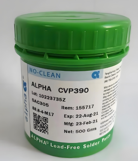
- Lead -free solder (for example, SAC305: SN96.5/AG3.0/Cu0.5)
- Melting point: ~ 217 ° C.
- Typical working temperature: 245 ° C to 270 ° C
- Benefits: Rohs that are appropriate, environmentally friendly
- Weakness: higher processing temperature, a slightly fragile joint
Lead -free solder has become a standard in modern electronic manufacturing due to environmental rules. However, it requires the right temperature control and time to ensure quality results.
Their polishing method and their temperature profile
Let’s explore how the soldering temperature varies in various processes used in the manufacture and assembly of PCB.
1. Solder Reflow
Solder Reflow is the most common method for assembling surface installation components. Pasta solder (mixture of powder solder and flux) is applied to PCB, and components are placed above. Then, the board passes through the oven reflow with a controlled temperature zone.
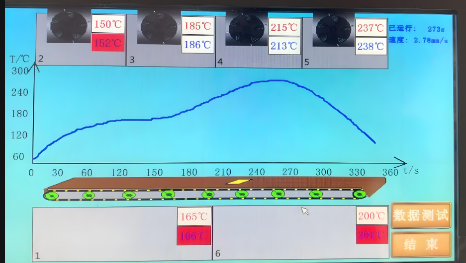
Reflow Temperature Profile (Lead Free):
- Heat: 150 ° Câ € “180 ° C for 60â €” 120 seconds
- Soak: 180 ° Câ € “200 ° C for 60â €” 90 seconds
- Reflow Peak: 240 ° Câ € “250 ° C for 30 – 60 seconds
- Cooling: Down to controlled room temperature
Reflow temperature profile (lead based):
- Heat: 120 ° Câ € “150 ° C.
- Soak: 150 ° Câ € “180 ° C.
- Reflow Peak: 210 ° Câ € “230 ° C.
- Cooling: Gradual cooling to avoid thermal shocks
The peak temperature must not exceed the maximum rating of the component, and the time above the liquidus (tal) must be maintained shortly to avoid damage to the board.
2. Solder wave
Solder waves are widely used for hole assemblies through and several PCBs of mixed technology. The board passes the liquid solder wave.
- Tin -based solder: 245 ° Câ € “255 ° C.
- Lead free solder: 260 ° Câ € “270 ° C.
Before reaching the solder wave, the PCB is heated to around 100 ° C ‘150 ° C to prevent thermal shocks and increase solder wetting. Flux is applied before the initial stage to clean and prepare bearings.
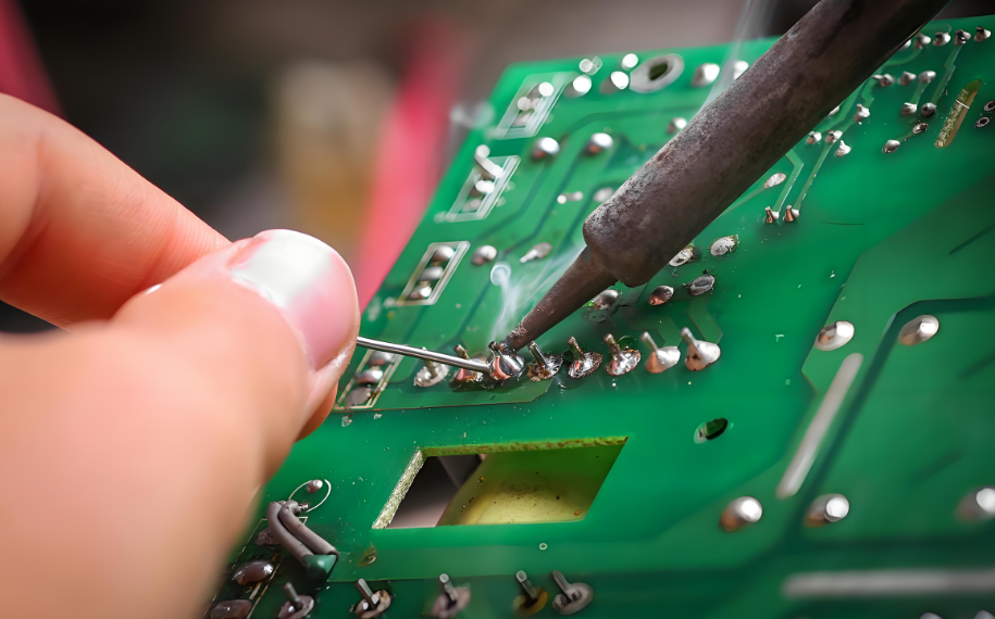
3. Solder Hand
Hand solders are still widely used in manufacturing prototypes, repair work, or in special low volume assemblies. It uses solder iron with a temperature controlled tip. The recommended tip temperature:
- Lead -based solder: 330 ° C to 370 ° C
- Lead free solder: 350 ° C to 400 ° C
Although this may seem high, the actual contact time is very short (1â € “3 seconds). A good solder station will allow proper control and thermal recovery. Operators must avoid bearings or components that are too hot.
Does PCB material affect the soldering temperature?
Yesâ € ”PCB material plays a major role in how much heat can be tolerated.
FR-4 (standard)
- Can handle up to 260 ° C for short duration
- Common for most PCBs of consumers and industry
High-TG FR-4
- Higher glass transition temperatures (Tg ~ 170 ° C to 180 ° C)
- More stable under high thermal pressure
- Ideal for the soldering board or lead -free multilayer
Ceramic PCB (Alumina, Aluminum Nitride)
- Very high thermal stability
- Can last 300 ° C+ without damage
- Requires a more appropriate soldering to avoid cracking
Metal core pcb (aluminum, copper core pcb)
- Hold up to 260 ° C for short duration
- Thermal conductivity is high because of the metal core
- Used in: Electronic Power, Lighting, and Automotive Control
Aluminum board removes heat quickly, which helps during the soldering. However, uneven expansion between metal and dielectric layer requires careful control to avoid mechanical stress during reflow.
Flexibly PC Circuit (PCB)
- Solder Max temperature: Usually <250 ° C
- Material: Polyimide or pet base
- Critical Risk: Heat can distort, shrink, or trace damage
Flexible PCB is more sensitive to heat than a stiff board. The basis of the polyimide or pet can tolerate the soldering but has a lower thermal mass, which means heating € “and cooling – faster. Excessive temperatures or contact time can easily cause:
- Wrinkles or warping
- Delamination of copper traces
- Tearing the bend area
When soldering flexible circuits:
- Use lower peak temperature reflowusually not exceeding 240 ° Câ € “245 ° C..
- Apply Thermal Obstacles or Pengaku in vulnerable areas.
- Make sure the heater and cool gradually to prevent mechanical stress.
Flex PCB often uses selective solder or low temperature solder to reduce heat exposure. In some cases, hot-bar solder or laser solder is used for better temperature precision.
General soldering problems related to temperature
| Problem | Cause | Prevention |
| Cold joint | The temperature is too low | Increase temperature or increase heat transfer |
| Component damage | The temperature is too high or too long | Shortening time, use the right profile |
| Soldering bridge | Excess solder, poor control | Use the right stencil and paste volume |
| PCB delamination | Too hot | Stay under TG and TD Board |
| Crack joint | Thermal shocks during cooling | Use the controlled cooling stage |
Why choose the best Solder PCB Technology service?
At most technology, we ensure that every PCB assembly follows strict soldering standards. Our team uses a professional thermal profile tool to perfect the temperature curve for each product.
We support:
- Tin free solder that matches Rohs
- Tin -based solder for special industries
- PCB TG and High Ceramics
- Automatic Reflow and Wave Solder
- Solder Manual by IPC Trained Operators
For example, you have questions about our products and services, prices, MOQ, shipping, location, quality standards, certificates, technical support and so on. We offer technical support, thermal profile, and high quality PCB manufacturing for all your assembly needs. Please contact us freely at any time. We aim to become the best PCB manufacturer in China to supply our customers with the best quality, price, and service. Contact us now to discuss your next PCB project or to request offers!
FAQ
1. What is the ideal soldering temperature for leadership free?
Peak reflow temperature 245 ° Câ € “250 ° C is typical. Manual solder may require an end temperature of 350 ° Câ €” 370 ° C.
2. Can I use the same temperature for lead solder and lead free?
No. Lead -free solder requires a higher temperature because of the higher melting point.
3. Will the high solder temperature damage my PCB?
If the temperature is too high or lasts too long, they can cause delamination, burning bearings, or component failure. Use the right profile.
4. What is the difference between peak temperature and tip temperature?
The peak temperature is the highest board temperature during reflow. Edge temperature is the heating surface of the iron during manual solder.
5. How can the best technology help with soldering specifications?
We provide detailed thermal profiles, polluderans that are safe for components, and high reliability assembly for all types of PCBs.
Tag: solder temperature for pcb
This entry was posted on Thursday, July 3, 2025 at 16:43 and submitted under the best PCB, BestTPCB, FAQ, FR4 PCB, PCB News, PCBA. You can follow any response to this entry through RSS 2.0 bait. You can leave a response, or trackback from your own site.
Game Center
Game News
Review Film
Berita Olahraga
Lowongan Kerja
Berita Terkini
Berita Terbaru
Berita Teknologi
Seputar Teknologi
Berita Politik
Resep Masakan
Pendidikan
Berita Terkini
Berita Terkini
Berita Terkini
review anime
Gaming Center
Originally posted 2025-07-07 01:57:53.