IMS PCB Complete form is an isolated metal substrate PCBThe type of printed circuit board built to manage high heat and maintain strong mechanical support. This is a popular choice for LED lighting, power supply, and automotive electronics, where hot control is very important.
In the best technology, we are a trusted IMS PCB manufacturer in China, providing special thermal management solutions with high precision, reliable materials, and various technical support. But let’s dig deeper about what makes PCB substrate metal unique isolated ‘and why they are so important in modern electronics.
What is IMS Insulated Metal Substrate PCB?
IMS PCB (isolated metal substrate) is a type of circuit board that uses the thermal conductive dielectric layer that is bound between metal base (often aluminum or copper) and copper circuit layer. Metal base helps eliminate heat more efficiently, especially compared to traditional FR4 boards.
When it comes to IMS PCB thermal conductivity, this is the most valuable feature. The dielectric layer on the IMS board usually offers the thermal conductivity range from 1.0 W/MK to more than 8.0 W/MK, depending on the application. Metal base, such as aluminum or copper, functions as a congenital heat sink € ”withdrawing heat from active components such as LEDs, power transistors, or ICs. That is why PCB STIs are generally used in LED modules, power converters, automotive lighting, and diesel inverters where the two heat and performance needed.
IMS PCB material
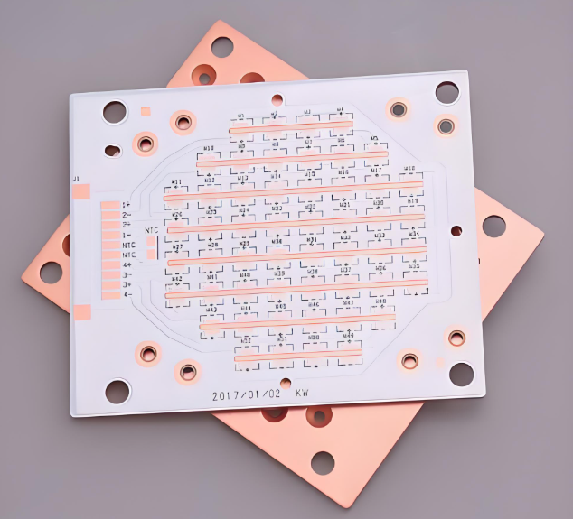
Choosing the right material for the IMS board is very important. Three layers form standard PCB IMS: metal base, dielectric layer, and copper foil. And for the base of the metal, there are two options: basic copper and aluminum.
Copper IMS PCB offers superior heat transfer capabilities. Copper has a thermal conductivity of nearly 400 W/MK, much higher than aluminum. This means that copper is ideal for applications with extreme power density or where space is limited but heat is a concern.
However, copper is also more expensive and heavier than aluminum, so it is generally reserved for high performance needs such as laser modules, RF circuits, or military class devices.
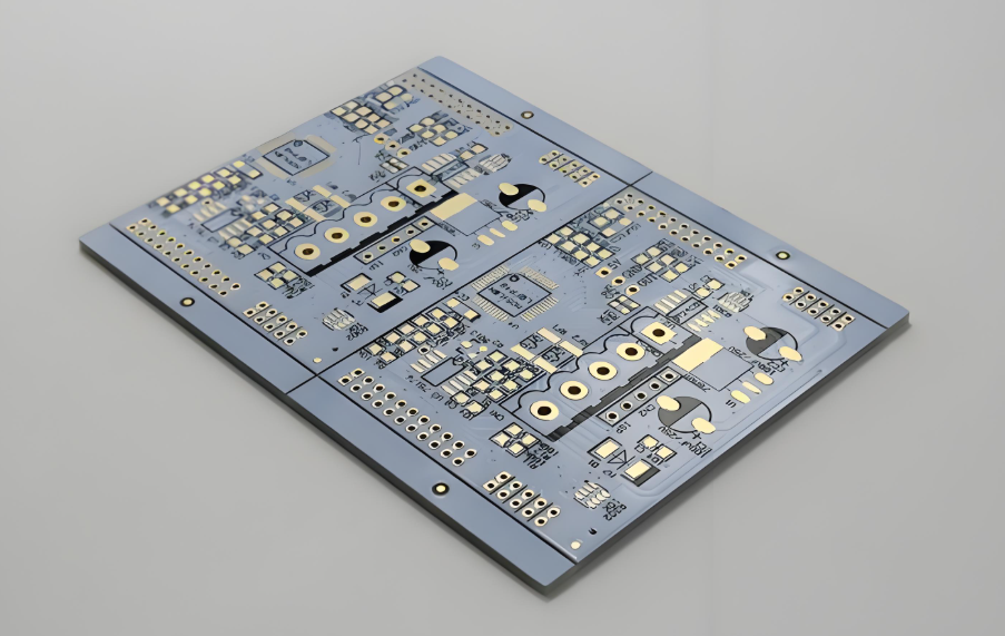
PCB Aluminum STI is the most common choice. Aluminum provides good thermal conductivity (usually around 200 W/MK), excellent mechanical strength, and lower costs compared to copper.
Aluminum IMS PCB is often used in LED lighting systems, electric vehicle charging, power control modules, and industrial automation systems. They provide a balanced solution between costs and thermal management, which is why they are industrial standards. Some common aluminum values used include:
- 5052 aluminum: strong, corrosion resistant, and suitable for structural use.
- 6061 Aluminum: Multipurpose Choir, High Power.
- 1060 Aluminum: Very good thermal conductivity, ideal for applications that are sensitive to costs.
IMS PCB Stackup
The IMS PCB pile refers to how the layer is set. The typical PCB IMS Stackup includes:
- Top Copper Trace Layer – for route and power signals.
- The thermal dielectric layer – usually made of epoxy resin filled with ceramics for heat transfer.
- Metal base – usually aluminum or copper.
For more sophisticated applications, PCB 2 IMS layers are often used. In 2 layers of IMS PCB, additional copper circuit layers are placed on a dielectric, and interconnection is formed using a hole through a hole. This is useful when you need a more complex stomach or a higher power density.
Multilayer IMS Stackup is possible but requires special laminated techniques. This is often adjusted depending on the mechanical needs, electricity, and thermal application.
IMS PCB Application
Thanks to their thermal performance and extraordinary mechanical strength, PCB STI is widely used in demanding environments. Here are some main application areas:
- LED lighting: street lights, high chandeliers, growing lights, automotive lights.
- Electronics Power: DC-DC converter, voltage regulator, motorcycle driver.
- Automotive System: Controlling Electric Vehicles, Battery Management Unit.
- Industrial equipment: robotics, welding machine, servo driver.
- Telecommunications: 5G base station, power amplifier.
- Renewable energy: Solar panel inverter, wind turbine converter.
PCB HS IMS Code
For companies that export or import PCB STIs, understanding HS code (harmonized system code) is very important for customs and compliance permits.
The general HS code for STI PCB is below:
8534.00 – Print Circuit
Subcategory can vary depending on whether the board is filled (assembled) or naked.
More correctly:
A. PCB Bare IMS (Unassembled):
- HS code 8534.00.90 (for 1-4 IMS PCB layers)
- HS code 8534.00.10 (4 or above the IMS PCB layer)
B. PCB of STIS is assembled:
HS Code 8537.10 or other depends on the classification and application of the final product.
Always check with the Customs Authority or local logistics provider for the right code that applies to the type of product and your destination country.
PCB assembly STI
PCB assembly IMS involves more maintenance than standard FR4 boards due to thermal management and mechanical stiffness. Special attention must be given to the solder profile and thermal expansion to prevent cracks or delamination.
Important points during assembly:
- Use a low stress pollucer method (for example, a controlled vapor or reflow phase).
- Make sure the right thermal profile during reflow to avoid damage to the base of the metal or isolation.
- Choose a mask and high solder component to handle high power density applications.
For high volume requirements, the SMT channels must automatically be optimized for heat dissipation and tight placement tolerance.
The best technology offers one -stop PCB assembly, including:
- DFM (Design for Production) & DFA Examination (Design for Assembly)
- SMT and Solder Hole
- Aoi, X-ray inspection
- Functional testing
- Assembly of building boxes
- Final inspection
Our strict quality control ensures your board is built to meet thermal and mechanical demands.
Best IMS PCB Manufacturers – Best Technology
When choosing the most important manufacturer, experience, quality, and IMS PCB adjustment ability. That’s where the best technology is prominent.
We specialize in the isolated metal substrate PCB with more than one decade of industrial focus. Our strength lies in the PCB of sophisticated thermal management, from the aluminum IMS board to the Multilayer-Inti Copper solution.
Why choose the best technology for PCB STI?
✅ Technical support before & after sales
✅ 99% customer satisfaction ISO9001, ISO13485, IATF16949, UL
✅ Material options: Various kinds of metal bases (Al, Cu, Stainless Steel), dielectric material with 1â € “8 W/MK.
✅ Full-Stack service: from DFM support to the assembly and final testing.
MES traceability: tracking and real time control throughout production.
✅ Technical support: special piles, prototyping, thermal analysis, and layout reviews.
Whether you need 2 layers of IMS PCB for automotive lighting or high -powered copper IMS boards for industrial drive, we can adjust the solution to suit your needs. With our strong supply chain and experienced teams, we help customers around the world turn on their design.
The best technology is your entry partner for the fabrication and assembly of Custom PCB. We combine in -depth technical knowledge, certified quality, and flexible manufacturing to provide a functioning solution.
Ready to improve your thermal management? Contact the best technology today for fast offers or technical consultations.
FAQ
1. What is the difference between IMS PCB and FR4 PCB?
IMS PCB uses a metal basis for better heat dissipation, while the FR4 board uses fiberglass, which has low thermal conductivity.
2. Can the IMS PCB layered?
Yes, Multilayer IMS PCB is possible but requires special laminated techniques and is more complex to be produced.
3. What is the typical thermal conductivity value for PCB STI?
The dielectric layer on the STI board usually ranges from 1 to 8 W/MK. Copper and aluminum also contribute to heat dissipation.
4. What is the HS code for the PCB of STIs that are assembled?
Usually, 8537.10, but check with the local customs authority because the code can vary by region.
5. How can I ask for a special PCB IMS quote from the best technology?
Just send an email to us your Gerber file, bombs, and design requirements, or use our online offer form. Our engineers will return to you quickly.
Tag: IMS PCB, IMS PCB Complete Form, Isolated Metal Substrate
This entry was posted on Tuesday, June 24, 2025 at 18:20 and submitted under the best PCB, BestTPCB, Design Guide, FAQ, MCPCB, PCB Core Metal. You can follow any response to this entry through RSS 2.0 bait. You can leave a response, or trackback from your own site.
Game Center
Game News
Review Film
Berita Olahraga
Lowongan Kerja
Berita Terkini
Berita Terbaru
Berita Teknologi
Seputar Teknologi
Berita Politik
Resep Masakan
Pendidikan
Berita Terkini
Berita Terkini
Berita Terkini
review anime
Gaming Center
Originally posted 2025-06-24 11:32:50.