What is STI PCB?
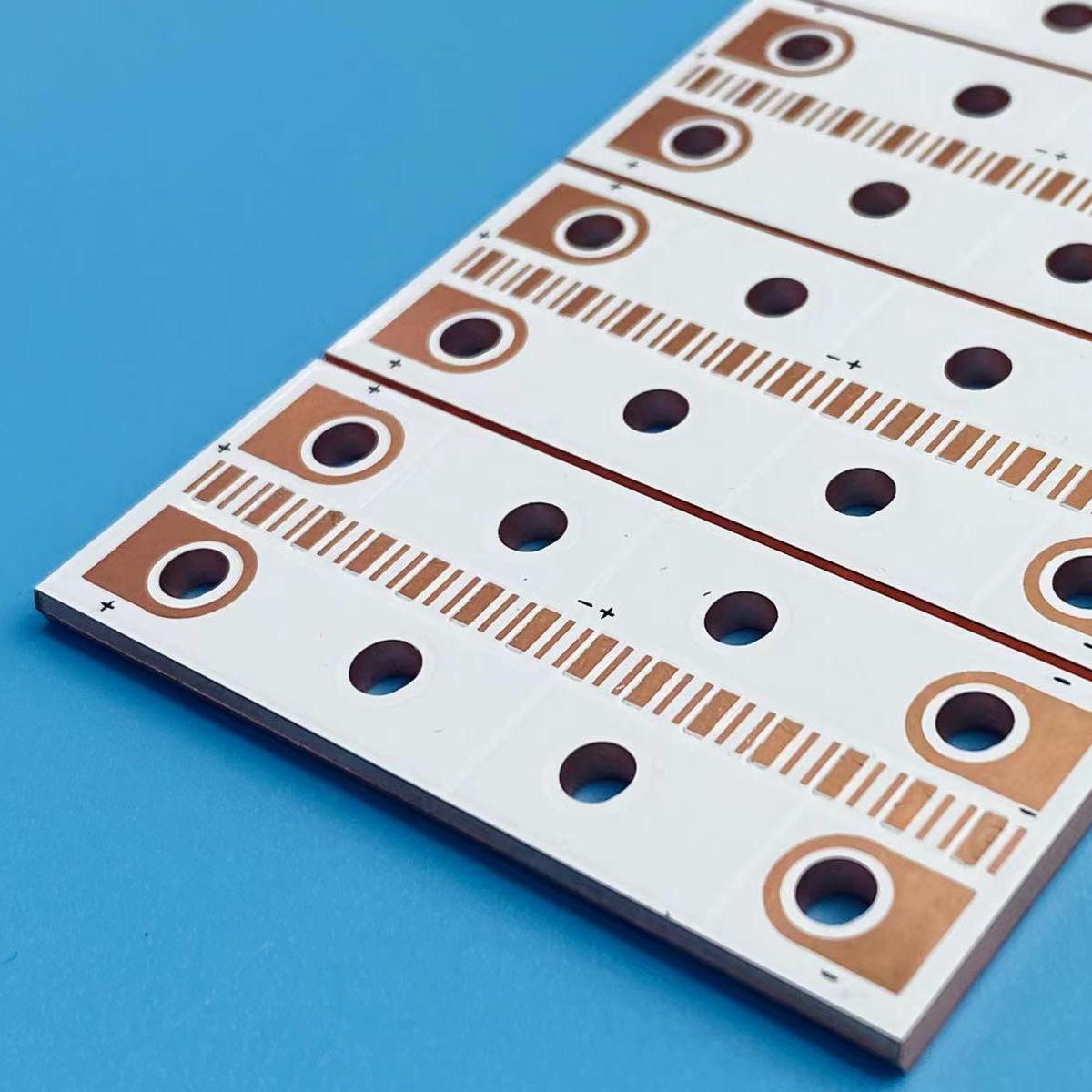
Unlike traditional PCBs that rely on FR4 or other resin -based materials, IMS PCB Use a metal base ”usually aluminum or copper. This base is paired with a dielectric layer and a coating layer of copper circuit on it.
This is not just a circuit board. This is the thermal solution that keeps the device cold and runs longer.
IMS PCB form and full meaning?
Complete form of IMS PCB isolated Metal substrate printing circuit board. This is a PCB built to move heat from components. That means better reliability, higher efficiency, and longer life for your electronic product.
In this type of PCB, the metal substrate acts as a heat spreader. The isolation layer isolation of copper circuit from the base of the metal, while it still allows heat to pass through. This is a smart design that balances performance with thermal control.
What is STI material?
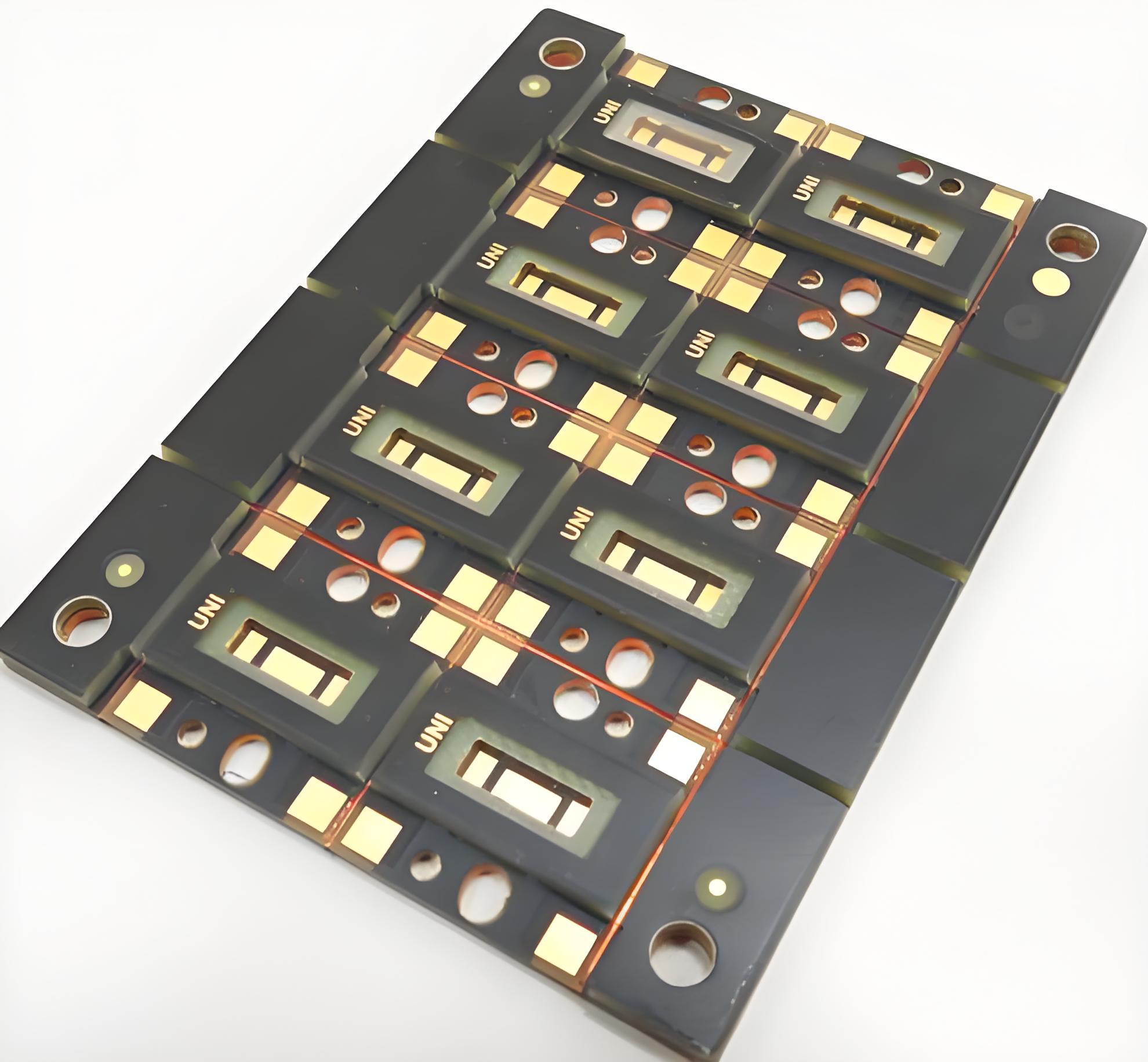
The essence of each IMS PCB located in the material. These layers provide the best thermal performance and electricity. This is what you find in the Standard IMS pile:
- Metal base layer: Usually aluminum for cost efficiency and light. Copper is also used when more heat dissipation is needed.
- Dielectric layer: Materials that are thermal conductive but electric insulation. It transferred the heat from the circuit layer to the metal base.
- Copper circuit layer: This is where the actual electrical routing occurs. This is similar to a traditional PCB copper layer but is optimized for thermal contact.
These three layers form the STI structure. This combination is compact, efficient, and strong, especially in LED lighting, automotive electronics, and power converters.
The isolation layer, in particular, must handle high thermal loads while withstanding electrical damage. Sophisticated IMS design often uses exclusive dielectric material to increase thermal conductivity and reduce overall thickness.
How thick is PCB STI?
Thickness IMS PCB Depending on the application. But usually, This is what you expect:
- Metal base layer: 0.5mm to 3.2mm
- Dielectric layer: 0.03mm to 0.2mm
- Copper layer: 0.035mm up to 0.2mm
Total thickness usually ranges from 0.8mm to 3.5mm. For LED lighting and compact modules, a thinner IMS board (like 1mm) is common. But in a heavy design, a thicker board provides the support and thermal capacity needed.
Some special buildings even exceed 3.5mm if the demand for extreme heat. A thicker aluminum layer increases mechanical strength and heat dissipation, but also increases weight and cost. So choosing the right thickness is the balance of thermal needs and design efficiency.
What is the difference between FR4 and IMS PCB?
PCB FR4 Use epoxy that is reinforced glass as its point. They are good for general electronics. But FR4 struggles with thermal stress. When the high power component becomes hot, FR4 is not enough to cool it. It leads to hot and failure.
IMS PCB, on the other hand, was built for thermal performance. The metal base acts like a default heat sink. It attracts heat from critical components and spreads it. It protects electronics and increases reliability.
| Feature | FR4 PCB | IMS PCB |
| Core Material | Epoxy -based fiberglass | Metal (usually aluminum) |
| Thermal conductivity | ~ 0.25 W/MK | 1.0â € “9.0 W/MK or more |
| Heat dissipation | Limited | Very good |
| Cost | Lower | A little higher, but commensurate |
| Mechanical strength | Currently | Stronger because of the metal nucleus |
For daily consumer electronics, FR4 is fine. But for power thirsty devices, PCB IMS offers unmatched reliability.
2 Layers of IMS PCB vs Multilayer IMS PCB
While the most common single IMS board, especially in LED lighting, 2-Lapis and Multilayer IMS PCB get land in complex applications.
2-Lather IMS PCB Means there is a copper circuit on both sides of the dielectric layer, with one metal core layer. It offers more stomach options while still allowing good heat dissipation.
PCB IMS MultilayerOn the other hand, it can include several copper layers, separated by insulation, and only one side is connected to the base of the metal for heat transfer. This allows for complex stomachs and high component density while maintaining thermal control.
Benefits of 2-Lather IMS PCB:
- Better circuit flexibility
- Medium thermal management
- More freedom of design
Benefits of Multilayer IMS PCB:
- High circuit complexity
- Suitable for solid power modules
- Thermal performance is still superior to FR4
If you build a simple LED module, a single or 2-layered IMS may be enough. But if you design a power control, communication device, or automotive ECU, Multilayer STIs are often needed.
IMS PCB Stackup: What to know?
Stackup design is more than just a layer, this defines how your boards handle heat, power, and performance. The typical PCB IMS Stackup looks like this:
- Dielectric insulation layer
- Metal substrate (usually aluminum)
But there is room for adjustment. This is what is important:
- Copper thickness: Choose 1oz, 2oz, or more depending on the flow of current.
- Dielectric performance: The higher the thermal conductivity (measured in W/MK), the better heat transfer.
- Metal base: Aluminum is a goal for most people. But copper or stainless steel can be used for extreme performance or stiffness.
- Surface finishing: Choose between Hasl, Enig, OSP, or others based on your assembly process.
Stackup options directly affect reliability. A bad choice here means the component will be too hot, the solder connection will be cracked, or the performance will go down.
What is the IMS PCB application?
IMS PCB is widely used in the high power industry.
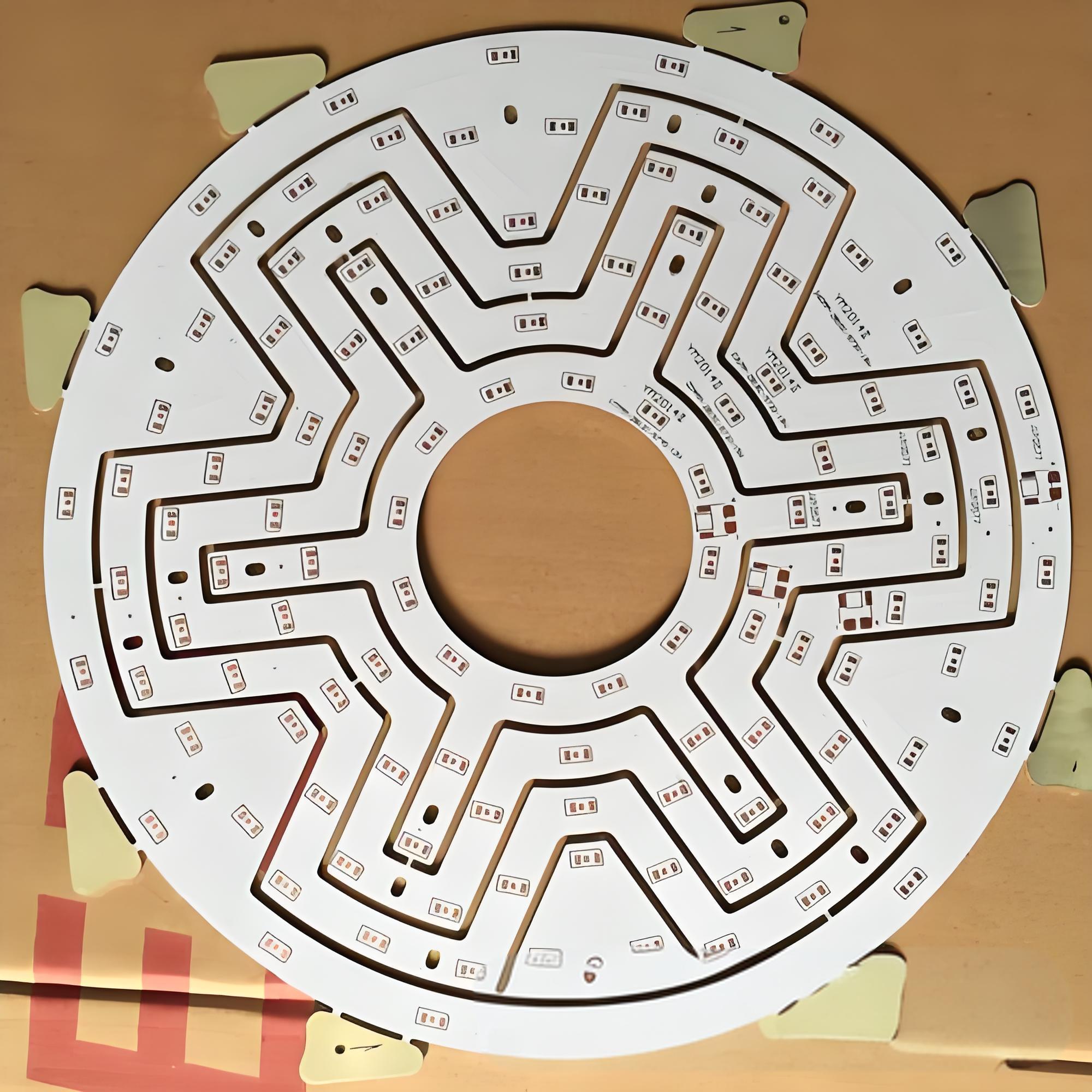
- LED lighting: Maintaining very open LEDs remain cold, extend their lives.
- Automotive Electronics: Used on the headlights, sensors, battery modules.
- Power Converters: Manage heat in the inverter and converter.
- Industrial Control System: Ensure smooth performance below high power load.
- Communication Pangkalan Station: Maintain signal integrity and prevent thermal damage.
Why Choose the Right IMS PCB Manufacturer?
On Best TechnologyWe understand the important role played by PCB STI. We have spent many years perfecting the production process, materials, and customization of stackups. Every board we send is tested to:
- Thermal conductivity
- Mechanical strength
- Electric reliability
Whether you need a standard single layer board or complex Multilayer IMS PCB, we can build it according to your needs.
Conclusion:
IMS PCB very important in high power electronics. From simple LED lights to sophisticated power modules, the STI board keeps your device cold, stable, and efficient.
Looking for an IMS PCB manufacturer that you can rely on? Contact us today at [email protected]
Tags: IMS PCB, PCB assembly IMS, IMS PCB material, IMS PCB Meaning, IMS PCB Structure
This entry was posted on Friday, July 25, 2025 at 18:07 and submitted under the best PCB, BestTPCB, MCPCB, Metal Core PCB. You can follow any response to this entry through RSS 2.0 bait. You can leave a response, or trackback from your own site.
Game Center
Game News
Review Film
Berita Olahraga
Lowongan Kerja
Berita Terkini
Berita Terbaru
Berita Teknologi
Seputar Teknologi
Berita Politik
Resep Masakan
Pendidikan
Berita Terkini
Berita Terkini
Berita Terkini
review anime
Gaming Center
Originally posted 2025-07-26 16:56:16.